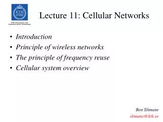
Week 13 lecture 2 Cellular Networks -- Interference
Week 13 lecture 2 Cellular Networks -- Interference. MAJOR LIMITING FACTOR for Cellular System performance is the INTERFERENCE Interferences can cause: CROSS TALK Missed and Blocked Calls. SOURCES OF INTERFERENCE? Another mobile in the same cell (if distance & frequency are close)

Week 13 lecture 2 Cellular Networks -- Interference
E N D
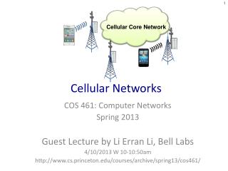
Presentation Transcript
MAJOR LIMITING FACTOR for Cellular System performance is the INTERFERENCE Interferences can cause: CROSS TALK Missed and Blocked Calls. SOURCES OF INTERFERENCE? • Another mobile in the same cell (if distance & frequency are close) • A call in progress in neighboring cell (if frequency is close). • Other base stations operating in the same frequency band (from co-channel cells) • Non-cellular systems leaking energy into cellular frequency band
Interference 1. CO-CHANNEL INTERFERENCE 2. ADJACENT CHANNEL INTERFERENCE
CO-CHANNEL INTERFERENCE • Frequency Reuse Given coverage area cells using the same set of frequencies co-channel cell !!! • Interference between these cells is called CO-CHANNEL INTERFERENCE. • However, co-channel interference cannot be overcome just by increasing the carrier power of a transmitter. Because increase in carrier transmit power increases the interference. • How to Reduce co-channel interference? Co-channel cells must be physically separated by a minimum distance to provide sufficient isolation.
Co-Channel Interference Cell Site-to-Mobile Interference (Downlink) Mobile-to Cell-Site Interferences (Uplink)
Co-Channel Interference (Base Mobile) : DOWNLINK (Mobile Base) : UPLINK UPLINK All mobiles (in 6 cells + central cell) assigned to the same frequency channel DOWNLINK All base stations (in 6 cells and central cell) have the same frequency channel. Note: if we allocate channels to a cell, part of the channels are used for “downlink”; the rest are for “uplink”.
Co-Channel Interference (Base Mobile ): DOWNLINK CASE From the base stations of co-channel cells: interference received by the mobile in the center cell. Desired signal is from the base to mobile in the center cell itself. Alarge is the area of the hexagonal cells of the large one. Asmall is the area of each cell. Alarge/Asmall A number of cells in this each repetitious pattern (3N).
Co-Channel Interference • Intracell Interference: interferences from other mobile terminals in the same cell. • Duplex systems • Background white noise • Intercell interference: interferences from other cells. • More evident in the downlink than uplink for reception • Can be reduced by using different set of frequencies • Design considerations: • Frequency reuse • Interference • System capacity • Bottomline: It determines link performance which in turn dictates the frequency reuse plan and overall capacity of the system.
Co-Channel Interference • For simplicity, we consider only the average channel quality as a function of the distance dependent path loss. • Signal-to-Co-channel interference ratio, (S/I), at the desired mobile receiver which monitors the forward channel is defined by • S is the desired signal power from desired base station • Ii is interference power caused by the i-th interfering co-channel cell’s base station. • NIis the number of co-channel interfering cells (NI = Cluster size –1)
Co-Channel Interference • The desired signal power S from desired base station is proportional to r -, where r is the distance between the mobile and the serving base station. is the path loss component. • Likewise, from power viewpoint, the received interference, Ii, between the ith interferer (base station) and the mobile is proportional to (Di)-. Assume the transmits powers from all base stations are equal, then we have
Co-Channel Interference Consider only the first tier of interfering cells, if all interfering base stations are equidistant from the desired base station and if this distance is equal to the distance D between cell centers, then the above equation can be simplified to: (i.e., r=R and assume Di=D and use q=D/R):
Co-Channel Interference • Thus Frequency reuse ratio, q e.g., NI = 6 • Example: for =4, S/I > 18dB (the larger, the better), q > (6101.8)1/4 = 4.41. (dB=10Logx) • The cluster sizeNshould be (from eq. q=sqrt(3N) N = q2/3 > 6.79 7. i.e.,A 7-cell reuse pattern is needed for an S/I ratio of 18dB. Based on q=D/R,we can select D by choosing the cell radius R.
Remember -- co-channel reuse ratio (Frequency Reuse Factor)q -- • q=sqrt(3N) • q=D/R • NI= Cluster size –1 • N =i2+ij+j2
Co-Channel Interference An S/I of 18 dB is the measured value for the accepted voice quality from the present day cellular mobile receivers. Sufficient voice quality is provided when S/I is greater than or equal to 18dB.
Example: Co-Channel Interference If S/I = 15 dB required for satisfactory performance for forward channel performance of a cellular system. • What is the Frequency Reuse Factor q (assume K=4)? • Can we use K=3? Assume 6 co-channels all of them (same distance from the mobile), I.e. N=7
Example: Co-Channel Interference • NI =6 => cluster size N= 7, and when =4 The co-channel reuse ratio is q=D/R=sqrt(3N)=4.583 Or 18.66 dB greater than the minimum required level ACCEPT IT!!! b) N= 7 and =3 Or 12.05 dB less than the minimum required level REJECT IT!!!
Example: co-Channel Interference We need a larger N (thus q is larger).Use eq. N =i2+ij+j2, for i=j=2 next possible value is N=12. q=D/R=sqrt(3N) =6 and =3 Or 15.56 dB N=12 can be used for minimum requirement, but it decreases the capacity (we already gave an example: when cluster size is smaller, the capacity is larger).
D+R R D+R D D D-R D-R Worst Case Co-Channel Interferencei.e., mobile terminal is located at the cell boundary where it receives the weakest signal from its own cell but is subjected to strong interference from all all the interfering cells. • We need to modify our assumption, (we assumed Di=D). • The S/I ratio can be expressed as Used D/R=q and =4. Where q=4.6 for normal seven cell reuse pattern.
Example: Worst CaseCochannel Interference (2) • A cellular system that requires an S/I ratio of 18dB. (a) if cluster size is 7, what is the worst-case S/I? (b) Is a frequency reuse factor of 7 acceptable in terms of co-channel interference? If not, what would be a better choice of frequency reuse ratio? • Solution (a) N=7 q = . If a path loss component of =4, the worst-case signal-to-interference ratio is S/I = 54.3 or 17.3 dB. (b) The value of S/I is below the acceptable level of 18dB. We need to decrease I by increasing N =9. The S/I is 95.66 or 19.8dB.
Example: Worst CaseCochannel Interference For a conservative estimate if we use the shortest distance (=D-R) then Or 14.47 dB. REMARK: In real situations, because of imperfect cell site locations and the rolling nature of the terrain configuration, the S/I ratio is often less than 17.3 dB. It could be 14dB or lower which can occur in heavy traffic. Thus, the cellular system should be designed around the S/I ratio of the worst case.
Example: Worst CaseCo-Channel Interference REMARK: • If we consider the worst case for a 7-cell reuse pattern • We conclude that a co-channel interference reduction factor of q=4.6 is not enough in an omnidirectional cell system. • In an omnidirectional cell system N=9 (q=5.2) or N=12 (q=6.0) the cell reuse pattern would be a better choice. • These cell reuse patterns would provide the S/I ratio of 19.78 dB and 22.54 dB, respectively.
2. ADJACENT CHANNEL INTERFERENCE Interference resulting from signals which are adjacent in frequency to the desired signal is called ADJACENT CHANNEL INTERFERENCE. WHY? From imperfect receiver filters (which allow nearby frequencies) to leak into the pass-band. NEAR FAR EFFECT: • Adjacent channel user is transmitting in very close range to a subscriber’s receiver, while the receiver attempts to receive a base station on the desired channel. • Near far effect also occurs, when a mobile close to a base station transmits on a channel close to one being used by a weak mobile. • Base station may have difficulty in discriminating the desired mobile user from the “bleedover” caused by the close adjacent channel mobile.
ADJACENT CHANNEL INTERFERENCE How to reduce? • Careful filtering • Channel assignment no channel assignment which are all adjacent in frequency. • Keeping frequency separation between each channel in a given cell as large as possible. e.g., in AMPS System there are 395 voice channels which are divided into 21 subsets each with 19 channels. • In each subset, the closest adjacent channel is 21 channels away. • 7-cell reuse -> each cell uses 3 subsets of channels. • 3 subsets are assigned such that every channel in the cell is assured of being separated from every other channel by at least 7 channel spacings.
Cell Splitting • A method to increase the capacity of a cellular system by dividing one cell into more smaller cells. • Cell splitting reduces the call blocking probability because the number of channels is increased. But it increases the handoff rate, i.e., more frequent crossing of borders between the cells. • We have the formula in calculating path loss: Pr(dBW) = P0(dBW) - 10 log10(d/d0) where d0is the distance from the reference point to the transmitter, and P0is the power received at the reference point.
Cell Splitting brings stronger Pr R • Let Pt1 and Pt2 be the transmit power of the large cell BS and medium cell BS, respectively. • From dB viewpoint, The received power at the edge of large cell is Pr1 = P0 - 10 log10(R/d0) • From non-dB viewpoint, The received power at the edge of large cell, Pr1 is proportional to Pt1 (R)- . • The received power at the edge of R/2 cell (small cell), Pr2 is proportional to Pt2 (R/2)- . • With the equal received power, we have Pt1 (R)-= Pt2 (R/2)- ,i.e., Pt1/Pt2= 2 R/2
Example – Cell Splitting Suppose each BS is allocated 60 channels regardless of the cell size. Find the number of channels contained in a 3x3 km2 area without cell splitting, (assume cell size R= 1km), and with cell splitting, R/2 = 0.5km. • The number of cells for R=1km. • Each large cell can cover 3.14km2, for 9 km2 approximately need 9/3.14 => 3 cells. However, N =i2+ij+j2. A better approximation is 4 cells. So the number of channels is 4x60=240. • With small cells, the number of cells (to cover 9 km2 ) is approximately 9 /(3.14x(1/0.5)2 )= 4 (last case) x4 = 16. Then the number of channels is 16x60=960.
Cell Sectoring(Directional Antennas) • Omni-directional antennas allow transmission of radio signals with equal power strength in all directions. • Reality is an antenna covers an area of 60 degrees or 120 degrees DIRECTIONAL ANTENNAS!!!! • Cells served by these antennas are called SECTORED CELLS !!! • Many sectored antennas are mounted a BS tower located at the center of the cell and an adequate number of antennas is placed to cover the entire 360 degrees of the cell. .
CELL SECTORINGDirectional Antennas (Sectoring) 1 1 2 2 4 3 3 90 DEGREE SECTOR 120 DEGREE SECTOR OMNIDIRECTIONAL 6 1 5 4 2 3 60 DEGREE SECTOR
Cell Sectoring(Directional Antennas) Advantages of Cell Sectoring: • Coverage of smaller area by each antenna and hence lower power is required in transmitting radio signals. • Helps to decrease interference between co-channels. • Increase frequency reuse since each sector can reuse the same set of frequency channels as in the parent cell. • Note that a quad-sector architecture (90) has higher capacity for 90% area coverage than a tri-sector (120) cell.
Co-Channel Interference Reductionwith the Use of Directional Antennas (Cell Sectoring) • The basic form of antennas are omnidirectional. Directional antennas can increase the system capacity. • If we sectorize the cell with 120o in each sector, the S/I becomes • The capacity increase is 3. 1 2 3 1 2 3 Note: now 1,2,3 can use the same channels since each antenna only covers its own sector (no leak to other sectors), i.e. NI= 2 instead of 6 now!
Fixed Channel Assignment (FCA) • Each cell is allocated a predetermined set of voice channels. • The BS is the entity that allocates channels to the requests. If all channels are used in one cell, it may borrow a channel from its neighbors through MSC. • Fast allocation, but may result high call blocking probabilities.
Dynamic Channel Assignment (DCA) • Voice channels are not allocated to each cell permanently. • When a request is received at the BS, this BS request a channel from MSC. • DCA can reduce the call blocking probability, but it needs real-time data collection and signaling transmission between BS and MSC.
Call Admission Control • CAC is used to avoid congestions over the radio links and to ensure the QoS requirements of ongoing services. • Quality of service (QoS) • Packet-level factors • Packet loss rate, packet delay, packet delay variation, and throughput rate. • Grade of service (GoS) • Call-level factors • New call blocking probability, handoff call dropping probability, connection forced termination probability.
CAC Procedure • Determine the amount of available channels, i.e., the number of channels for accepting new and handoff requests. • When the N-th request arrives, i.e., there are (N-1) ongoing services. • If there are enough resources to admit the N-th request, then the new request is admitted. • Otherwise, it will be denied. • In order to maintain the continuity of a handoff call, handoff calls are given higher priority than the new call requests. • The prioritized call admission is implemented by reserving channels for handoff calls. This method is referred to as guard channels. • Fixed reservation and dynamic reservation.
Cell Capacity • The average number of mobiles requesting service in unit time (average call arrival rate): • The average length of time a mobile requires service (the average holding time): T • The offered traffic load: a =T • e.g., in a cell with 100 mobiles, on an average, if 30 requests are generated during an hour, with average holding time T=360 seconds, then the arrival rate =30/3600 requests/sec. A servicing channel that is kept busy for 1 hour is quantitatively defined as 1 Erlang. Hence, the offered traffic load (a) by Erlang is then
Call Blocking • How likely a new user can get a connection established successfully? Admission control of new calls. • It is measured by the probability of call blocking, which is a quality of service (QoS) factor, a.k.a., (GoS) factor. • Assume we have a total number of S channels in a radio cell. • If the number of active users during any period of time is S, then the call blocking probability is 1. • If and only if the number of ongoing calls is less than S, the probability of call blocking will be less than 1.
Summary • The advantage of cellular communications • Capacity extension by frequency reuse • Cell cluster and cochannel cells • Number of cells in a cluster • Frequency reuse ratio • Cochannel interference • Impact of cluster size • Worst-case cochannel interference • Traffic load and call blocking probability • Average delay • Probability of queuing delay • Cell splitting and sectoring • Fixed channel allocation and dynamic channel allocation