Cellular Networks
Cellular Core Network. Cellular Networks. COS 461: Computer Networks Spring 2013 Guest Lecture by Li Erran Li, Bell Labs 4/10/2013 W 10-10:50am http://www.cs.princeton.edu/courses/archive/spring13/cos461/. Mobile Data Tsunami Challenges Current Cellular Technologies.

Cellular Networks
E N D
Presentation Transcript
Cellular Core Network Cellular Networks COS 461: Computer Networks Spring 2013 Guest Lecture by Li Erran Li, Bell Labs 4/10/2013 W 10-10:50am http://www.cs.princeton.edu/courses/archive/spring13/cos461/
Mobile Data Tsunami Challenges Current Cellular Technologies Source: CISCO Visual Networking Index (VNI) Global Mobil Data Traffic Forecast 2011 to 2016 • Global growth 18 times from 2011 to 2016 • AT&T network: • Over the past five years, wireless data traffic has grown 20,000% • At least doubling every year since 2007 • Existing cellular technologies are inadequate • Fundamental redesign of cellular networks is needed
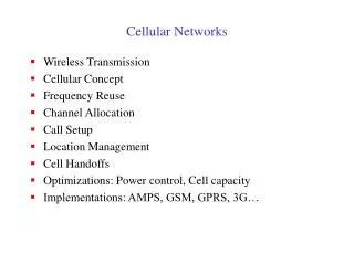
Outline Goal of this lecture: understand the basics of current cellular networks • Physical Layer • Access Procedure • Why no carrier sensing • Connection Setup • Mobility Management • Power Management and Mobile Apps • Differences between 3G and LTE • What is Next • Conclusion
Physical Layer: UMTS Code Division Multiple Access (CDMA) • Use of orthogonal codes to separate different transmissions • Each symbol or bit is transmitted as a larger number of bits using the user specific code – Spreading • Spread spectrum technology • The bandwidth occupied by the signal is much larger than the information transmission rate • Example: 9.6 Kbps voice is transmitted over 1.25 MHz of bandwidth, a bandwidth expansion of ~100
Physical Layer: LTE One resource block 12 subcarriers during one slot (180 kHz × 0.5 ms) One resource element 12 subcarriers One OFDM symbol One slot frequency Time domain structure Frame (10 ms) • The key improvement in LTE radio is the use of OFDM • Orthogonal Frequency Division Multiplexing • 2D frame: frequency and time • Narrowband channels: equal fading in a channel • Allows simpler signal processing implementations • Sub-carriers remain orthogonal under multipath propagation time Slot (0.5 ms) Subframe (1 ms)
Physical Layer: LTE (Cont’d) • Orthogonal Frequency Division Multiple Access (OFDM) • Closely spaced sub-carriers without guard band • Each sub-carrier undergoes (narrow band) flat fading - Simplified receiver processing • Frequency or multi-user diversity through coding or scheduling across sub-carriers • Dynamic power allocation across sub-carriers allows for interference mitigation across cells • Orthogonal multiple access T large compared to channel delay spread 1 T Frequency Narrow Band (~10 Khz) Wide Band (~ Mhz) Sub-carriers remain orthogonal under multipath propagation
Physical Layer: LTE (Reverse link OFDM) • Users are carrier synchronized to base station • Differential delay between users’ signals at the base need to be small compared to symbol duration User 1 W • Efficient use of spectrum by multiple users • Sub-carriers transmitted by different users are orthogonal at the receiver • - No intra-cell interference • CDMA uplink is non-orthogonal since synchronization requirement is ~ 1/W and so difficult to achieve User 2 User 3
LTE Scheduling: Downlink • Assign each Resource Block to one of the terminals • LTE – channel-dependent scheduling in time and frequency domain • HSPA – scheduling in time-domain only Time-frequency fading, user #2 Time-frequency fading, user #1 User #1 scheduled User #2 scheduled 1 ms Time 180 kHz Frequency
LTE Scheduling: Uplink • Each color represents a user • Each user is assigned a frequency-time tile which consists of pilot sub-carriers and data sub-carriers • Block hopping of each user’s tile for frequency diversity Frequency Typical pilot ratio: 4.8 % (1/21) for LTE for 1 Tx antenna and 9.5% for 2 Tx antennas Time • Pilot sub-carriers
Physical Layer LTE vs WiFi • Speed: LTE is designed to operate with a maximum mobile speed of 350km • Shorter channel coherence time, more frequent pilot transmissions • Coverage: several kilometers • Larger delay spread, more guard time overhead
Access Procedure Base station UE 2 UE 1 • Cell Search • Base station broadcasts synchronization signals and cell system information (similar to WiFi) • UE obtains physical layer information • UE acquires frequency and synchronizes to a cell • Determine the start of the downlink frame • Determine the cell identity • Random access to establish a radio link
Random Access UE Base station Core network Step 1: random access request (pick one of 64 preambles) Step 2: random access response Adjust uplink timing Step 3: transmission of mobile ID Only if UE is not known in Base station Step 4: contention resolution msg If ID in msg matches UE ID, succeed. If collision, ID will not match!
Random Access (Cont’d) Why not carrier sensing like WiFi? • Base station coverage is much larger than WiFi AP • UEs most likely cannot hear each other • How come base station can hear UEs’ transmissions? • Base station receivers are much more sensitive and expensive Base station UE 2 UE 1
LTE Architecture • UE: user equipment • eNodeB: base station • S-GW: serving gateway • P-GW: packet data network gateway • MME: mobility management entity • HSS: home subscriber server eNodeB 1 Cellular Core Network MME/HSS eNodeB 2 S-GW 1 UE 1 P-GW Internet and Other IP Networks eNodeB 3 S-GW 2 UE 2 GTP Tunnels
Connection Setup MME Session Request S-GW P-GW UE • Session Requests • UE to base station • Base station to MME • MME obtains subscriber info from HSS, selects S-GW and P-GW • S-GW sends to P-GW • P-GW obtains policy from PCRF
Connection Setup (Cont’d) MME S-GW P-GW UE Session Response • Session Response • Establishes GPRS Tunnels (GTP) between S-GW and P-GW, between S-GW and UE • Base station allocates radio resources to UE
Mobility Management MME UE S-GW P-GW Handoff • Handoff without change of S-GW • No change at P-GW • Handoff with change of S-GW or MME • Inter-technology handoff (LTE to 3G)
Mobility Management (Cont’d) MME Paging Request S-GW P-GW UE RRC_IDLE Packet received Paging • If S-GW receives a packet to a UE in IDLE state, inform MME • MME pages UE through base station
Power Management: LTE • UE runs radio resource control (RRC) state machine • Two states: IDLE, CONNECTED • Discontinuous reception (DRX): monitor one subframe per DRX cylce; receiver sleeps in other subframes Courtesy:Morley Mao
Power Management: UMTS Tail Time Delay: 1.5s Delay: 2s Tail Time Courtesy: Feng Qian State promotions have promotion delay State demotions incur tail times
Example in Detail: RRC State Machinefor a Large Commercial 3G Network Tail Time Waiting inactivity timers to expire DCH: High Power State (high throughput and power consumption) FACH: Low Power State (low throughput and power consumption) IDLE: No radio resource allocated DCH Tail: 5 sec FACH Tail: 12 sec Promo Delay: 2 Sec Courtesy: Feng Qian
Example in Detail: Pandora Music Problem: High resource overhead of periodic audience measurements (every 1 min) Recommendation: Delay transfers and batch them with delay-sensitive transfers Courtesy: Feng Qian
Why Power Consumptions of RRC States so different? • IDLE: procedures based on reception rather than transmission • Reception of System Information messages • Cell selection registration (requires RRC connection establishment) • Reception of paging messages with a DRX cycle (may trigger RRC connection establishment) • Location and routing area updates (requires RRC connection establishment)
UMTS RRC State Machine (Cont’d) • CELL_FACH: need to continuously receive (search for UE identity in messages on FACH), data can be sent by RNC any time • Can transfer small data • UE and network resource required low • Cell re-selections when a UE moves • Inter-system and inter-frequency handoff possible • Can receive paging messages without a DRX cycle
UMTS RRC State Machine (Cont’d) • CELL_DCH: need to continuously receive, and sent whenever there is data • Possible to transfer large quantities of uplink and downlink data • UE and network resource requirement is relatively high • Soft handover possible for dedicated channels and Inter-system and inter-frequency handover possible • Paging messages without a DRX cycle are used for paging purposes
LTE vs UMTS (3G): Architecture PDN GateWay Serving GateWay PGWSGW MME Mobility Management Entity (not user plane functions) Node B • PGW/SGW • Deployed according to traffic demand • Only 2 user plane nodes (non-roaming case) eNodeB • RNC functions moved to eNodeB. • No central radio controller node • OFDM radio, no soft handover • Operator demand to simplify • Control plane/user plane split for better scalability • MME control plane only • Typically centralized and pooled • Functional changes compared to the current UMTS Architecture GGSN SGSN RNC
LTE vs UMTS (3G): Physical Layer • UMTS has CELL_FACH • Uplink un-synchronized • Base station separates random access transmissions and scheduled transmissions using CDMA codes • LTE does not have CELL_FACH • Uplink needs synchronization • Random access transmissions will interfere with scheduled transmissions
What Is Next? LTE Evolution Dynamic Spectrum Sharing Base Station with Large Number of Antennas Software Defined Cellular Networks
LTE Evolution • LTE-A – meeting and exceeding IMT-Advanced requirements • Carrier aggregation • Enhanced multi-antenna support • Relaying • Enhancements for heterogeneous deployments LTE-C Rel-14 Rel-13 LTE-B Rel-12 LTE-A Rel-11 LTE Rel-10 Rel-9 Rel-8
LTE Evolution • LTE-B • Work starting fall 2012 • Topics (speculative) • Device-to-device communication • Enhancements for machine-to-machinecommunication • Green networking: reduce energy use • And more… LTE-C Rel-14 Rel-13 LTE-B Rel-12 LTE-A Rel-11 LTE Rel-10 Rel-9 Rel-8
Base Station with Large Number of Antennas Pilots Time • M base station antennas service K terminals, M>>K • Reduced energy (Joules/bit) plus increased spectral efficiency (bits/sec/Hz) • All complexity is with the service-antennas • No cooperation among cells
Base Station with Large Number of Antennas (Cont’d) Antennas Prototype front view
Base Station with Large Number of Antennas (Cont’d) 2. WARP Modules 1. Central Controller 4. Interconnects 3a. Clock Distribution 3c. Sync Distribution 3b. Ethernet Switch 3. Switch • Prototype back view
CellSDN Architecture • CellSDN provides scalable, fine-grain real time control with extensions: • Controller: fine-grain policies on subscriber attributes • Switch software: local control agents to improve control plane scalability • Base stations: remote control and virtualization to enable flexible real time radio resource management
CellSDN Architecture (Cont’d) Mobility Manager Subscriber Information Base Policy and Charging Rule Function Infra-structure Routing Radio Resource Manager Translates policies on subscriber attributes to rules on packet header Network Operating System: CellOS Offloading controller actions, e.g. change priority if counter exceed threshold Cell Agent Cell Agent Cell Agent Central control of radio resource allocation Packet Forwarding Hardware Packet Forwarding Hardware Radio Hardware
CellSDN Virtualization Network OS (Slice 1) Network OS (Slice 2) Network OS (Slice N) Slicing Layer: CellVisor Slice semantic space, e.g. all roaming subscribers, all iPhone users Cell Agent Cell Agent Cell Agent Packet Forwarding Hardware Packet Forwarding Hardware Radio Hardware
Conclusions • LTE promises hundreds of Mbps and 10s msec latency • Mobile apps need to be cellular friendly, e.g. avoid periodic small packets, use push notification services • Roaming and inter-technology handoff not covered • Challenges • P-GW central point of control, bad for content distribution, and scalable policy enforcement • Mobile video will be more than half of the traffic • Needs lots of spectrum (spectrum crunch)