Download
1 / 33
340 likes | 540 Vues
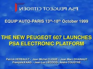
EQUIP’AUTO-PARIS 13 th -18 th October 1999 THE NEW PEUGEOT 607 LAUNCHES PSA ELECTRONIC PLATFORM Patrick HERBAULT - Jean Michel CLIQUE – Jean Marc DHAINAUT François KAAG - Jean Luc LECOCQ - André COUSTRE. ELECTRONIC PLATFORM. PSA vehicle development is now based on four vehicle platforms :

E N D
EQUIP’AUTO-PARIS 13th-18th October 1999 THE NEW PEUGEOT 607 LAUNCHESPSA ELECTRONIC PLATFORM Patrick HERBAULT - Jean Michel CLIQUE – Jean Marc DHAINAUTFrançois KAAG - Jean Luc LECOCQ - André COUSTRE
ELECTRONIC PLATFORM • PSA vehicle development is now based on four vehicle platforms : • PF1 platform 1 for small vehicles • PF2 platform 2 for medium sized vehicles • PF3 platform 3 for upper class vehicles • Co-operation platform for vehicle in collaboration with other car manufacturers • The benefits of platform strategy are well known and are reinforced concerning electronics • The ultimate objective is to reach a single electronic platform
THE TARGETED ELECTRICAL/ELECTRONIC ARCHITECTURE • It is based on : • An Intelligent Switching Unit ,so called ISU • A simultaneous optimisation of electrical architecture & electronic architecture. • That has been obtained by : • Optimised partitioning of harnesses minimising numberof interconnections • Merging an increasing number of body electronics functions in the ISU • Intensive use of the multiplexing technology
MULTIPLEXING TECHNOLOGIES • Historically different classes of multiplexing have been defined : • class A for low speed, master/slave low cost multiplexing • class B for medium speed multimasters multiplexing • class C for high speed multimasters multiplexing • class D for optical data link
CONTROLLER CONTROLLER CONTROLLER CONTROLLER CONTROLLER sensors display actuators SLAVE peripherals CONTROLLER AREA NETWORK CONTROLLER CONTROLLER CONTROLLER CONTROLLER sensors display actuators Vehicle Area Network VAN-CONCEPT
THE MAIN CHARACTERISTICS OF VAN STANDARD ISO PROTOCOL 11519-3 • Multimasters / multislaves architecture • Bitwise arbitration access method • Self clocking for slave peripherals • Fault tolerant bus driver able to cope with open or short circuit on one wire • 28 data bytes (up to 220 possible) protected by a 15 bits CRC • Broadcast or confirmed point to point communication • Deterministic behaviour through : • number of retries under control • control / command mechanism • In Frame Response mechanism
MASTER "Request" (Rank 0) Start of frame Adress Command 1 VAN In Frame Response Mechanism
MASTER "Request" (Rank 0) Start of frame Adress Command ACK PERIPHERAL "Answer" (Rank 16) Frame Cherk Sequence 0 Data(s) EOD Frame Cherk Sequence Start of frame RESULT Data(s) EOD ACK Adress Command Remote Transmission Request bit (RTR) VAN In Frame Response Mechanism
IMPLEMENTATION OF3 MULTIPLEXED NETWORKS • 1 CAN intersystem network short messages oriented at high speed • for mechanical and engine functions • multimasters network • speed = 250 kbits/s • message length allows 8 data bytes maximum (mathematical limitation) • 1 VAN comfort network long message oriented at medium speed • for display, dashboard, radio, climate, navigation functions ... • multimasters network • speed = 125 kbits/s • message length allows 28 data bytes maximum (possible extension to 220 bytes) fully matching with display equipment’s requirements. • 1 VAN body network safety and/or cost effective oriented • for airbags, front lights, doors, window lift, seats ... • master/slaves network less sophisticated but safer • typical speed 62.5 kbits /s which can be tuned for each slave node • message length = 28 data bytes max. • easy to add new nodes and sub-networks • In addition the diagnosis on the VAN nodes is transmitted on the VAN bus according to ISO 9141 procedures (compatible with the 28 data bytes length) to the ISU used as a gateway to transmit the DIAG on VAN to a 9141 connection
ISU SOFTWARE ARCHITECTURE • Another cost optimisation consists of incorporating in the ISU an increasing number of body electronics functions • To manage the merging of different body electronics functions we had to manage also the merging of competence's of the different body electronics suppliers • In order to succeed this merging, the hardware and the software development of the ISU have been separated • The separation of the hardware and software development is very usual in the computer science field, but had never been practised by PSA previously
PC WINDOWS Scanner Device Driver Printer Device Driver PRINTER SCANNER Mother Board (IBM, COMPAQ…) PC OPEN SOFTWARE ARCHITECTURE BIOS (Basic Input/Output Software)
ISU PSA Operating System Visibility Software Package Information Software Package DASHBOARD RAIN SENSOR ISU hardware (SAGEM, VALEO, SIEMENS) Non multiplexed connections Intersystem CAN Body VAN Comfort VAN ISU OPEN SOFTWARE ARCHITECTURE ADAPTED FROM PC WORLD BIOS (Basic Input/Output Software)
THE NEW PEUGEOT 607 will launch the new PSA electronic platform • Up to 24 electronic equipment's are interconnected through 5 electronic busses : • CAN intersystem network • VAN comfort network • VAN body network 1 dedicated to highly safety critical functions(airbag, headlights switching,…) • VAN body network 2 for the other functions(door control, seat control, fuel additivation requested by particle filter for the multi-valve Hdi diesel engine,…) • an optical data link D2B on optical fibre for large data transfer between the navigation system and the multifunction display
607, ISU SOFTWARE STRUCTURE Package function equipment Suppliers BIOS ISU SAGEM 1 theft protection transponder DELPHI/TEXTON 2 remote control HF VALEO 3 information dashboard VDO 4 windscreen vision rain sensor VALEO/ITT 5 lighting twilight sensor VALEO 6 seat memorisation memo box BITRON 7 door control central lock MAGNETI-MARELLI
Thanks to multiplexing, the 607 getsbenefit of the following functions : • Ignition key with multi-function remote control, called "plip” setting automatically seat & mirrors multiple adjustments • Detection of tyre under-inflation • Automatic hazard lights operation on fierce braking • Automatic switching on of the lights according twilight sensor • Display intensity varied to suit the ambient light conditions • Radio, radiophone volume control in line with speed • Parking assistance with special mirror positioning while moving in reverse for a better view of the kerb • Automatic wiper speed control including automatically switching of the sidelights • Engine intelligent service indicator taking into account real use of the vehicle
Immediate consequence on wiring : previous previous number future number differencevehicle of wires of wires PSA ELECTRONIC PLATFORM DEPLOYMENT • This electrical/electronic platform based on a set of around 20 electronic equipments including a biVAN-CAN ISU associated to an open multisuppliers software architecture is deployed on the four PSA vehicles platforms Citroën Xantia 670 429 - 36% Peugeot 306 635 373 - 41%
Volume Year NUMBER OF MILLIONS OF VANNODES PER YEARS
40 MILLIONS VAN COMPONENTS PER YEARWILL ALLOW COST EFFECTIVE CHIPS • VAN bus transceiver with watchdog, wake up and fault tolerance for less than 1 Euro from Alcatel or Elmos • VAN bus controller for less than 1 Euro from Atmel-MHS or NEC • ASIC VAN-IO16 (16 inputs/outputs) for also less than 1 Euro from Atmel • 8 bit microprocessors with VAN cell starting at 1.5 Euro from NEC • 32 bit microprocessor VANSTORM (2 VAN cells & 1 CAN cell) from NEC starting at 5.5 Euro
VAN NODE STRUCTURE Technologies ISO levels APPLICATION LLC layer CMOS VAN protocol handlerBus fault diagnosis MAC layer TX R1 R0 R2 Vref BiCMOS Supply physical layer FILTER VAN bus DATA DATAb +12V Gnd
Nominal mode is differential mode Technologies ISO levels APPLICATION LLC layer CMOS VAN protocol handlerBus fault diagnosis MAC layer TX R1 R0 R2 Vref BiCMOS Supply physical layer FILTER VAN bus DATA DATAb +12V Gnd
Single wire mode in case of failure of one wire Technologies ISO levels APPLICATION LLC layer CMOS VAN protocol handlerBus fault diagnosis MAC layer TX R1 R0 R2 Vref BiCMOS Supply physical layer FILTER VAN bus DATA DATAb +12V Gnd
Single wire mode in case of failure of one wire Technologies ISO levels APPLICATION LLC layer CMOS VAN protocol handlerBus fault diagnosis MAC layer TX R1 R0 R2 Vref BiCMOS Supply physical layer FILTER VAN bus DATA DATAb +12V Gnd
VAN Core VAN UART VAN slave Full VAN VAN VHDL MODELSavailable on web site http://www.van-mux.org • Industrialised by Thomson DETEXIS • full RTL model • no buffering (MAC level) • 3.5k gates maxi • Already used as a µcontroller cell • based on VAN core • 1 byte buffering • 3.5 k gates • Existing ASICs • based on VAN core • 5k gates • In development • based on VAN Core • 128 bytes RAM (adaptable to Silicon founders) • 14 identifier registers • 15k gates
FUTURE EXTENSION OF MULTIPLEXING • The further developments concern : • extension of multiplexing through ASIC developments : VAN IO8 down to VAN IO2 and VAN-MIX • evolutions of physical layers : pulse mode and spread spectrum technique • introduction of multimedia bus • introduction of firing bus for airbags • safety enhancement through VAN&CAN redundancy and TTP proposal • evolution from PSA local Operating System towards OSEK/VDX standard
FIRING BUS FOR AIRBAGS • In this safety critical application, the VAN-ISO 11519-3 gives already a standardised solution including : • master/slave operation • fault tolerant bus transceiver • available VHDL description (on web site : http://www.van-mux.org) • self-clocking for slave node allowing absence of local crystal or resonator and also adaptive speed : • 16.5 kbits/s for permanent diagnosis with low emission, • 250 kbits/s for firing
Slave peripherals Airbag 1 Airbag 2 CAN VAN VAN VAN CAN CAN Airbag system Airbag 3 ISU VAN Airbag 4 PROPOSAL FOR SAFETY CRITICAL APPLICATION As Example : Airbag system using VAN for firing BUS
OSEK / VDX • The open multisuppliers software architecture of PSA is based on a local Operating System which is a first step to prepare OSEK / VDX implementation • The next steps provided by OSEK / VDX will be : • first a standardised software kernel • second the evolution towards distributed functions
CONCLUSIONS The PSA electrical/electronic platform based on a set of 20 electronic equipment’s including a biVAN-CAN ISU associated to an open multisuppliers software architecture, - is launched on the new Peugeot 607 - will be deployed on the four PSA platforms