PLC Fundamentals Mod. 3
PLC Fundamentals Mod. 3. Programming with Function Blocks. Module Objectives. Upon successful completion of this module, students will be able to: Gain an overview of the important basic PLC concepts and functions in control technology.

PLC Fundamentals Mod. 3
E N D
Presentation Transcript
PLC FundamentalsMod. 3 Programming with Function Blocks
Module Objectives • Upon successful completion of this module, students will be able to: • Gain an overview of the important basic PLC concepts and functions in control technology. • Demonstrate how different logic functions work, such as the AND,OR and NOT. • Represent logic function operations in truth tables. • Use the timing and counting functions in programs. • Gain an overview of the most important functions of LOGO!Soft. • Create and test control programs using function blocks. • Demonstrate how to transfer programs from the PC to the LOGO! controller.
Useful Websites • http://www.mekanizmalar.com/logic_gates.html • http://www.wisc-online.com/Objects/ViewObject.aspx?ID=dig1302
3.1 Boolean Equations • Boolean equations: consist of variables and operations and look very similar to normal algebraic equations. • The three basic operators are AND, OR and NOT. • A·B=B·A • A+B=B+A • Truth table is a simple method for showing all the possible combinations that will turn an output ON or OFF.
Logic Functions • PLC Systems execute logic functions. Therefore, understanding logic functions of binary numbers is important for PLC programming. The basic logic functions include AND, OR, NOT, NAND, NOR & EXOR. • AND Function: AND function has two or more inputs and only one output. It produces a HIGH output only when all its inputs are HIGH. • Boolean Expression: P1=S1.S2
OR Function: OR function has two or more inputs and only one output. It produces a HIGH output only if one or more of the inputs are HIGH.
NOT Function: A NOT function has only one input and one output. It produces an output that is opposite to the input. Boolean Expression: P1=S1
3.2 Logic Design • To design logic circuits for a particular application it is important to describe how a controller works. • In order to describe the actual condition for a controller to work, it is usually expressed in terms of a Boolean equation. • In this case it is written out in the form of a sentence first, and then converted to a Boolean expression. • The Boolean expression may then be converted to a desired form: either the Function Block Diagram (FBD) or the Ladder Diagram (LAD).
Class Activity: “Example” • A machine can be only switched ON if its door is closed (this can be sensed using a limit switch) and two pushbuttons are pressed. Write down the Boolean expression for this problem. • 1. To find the Boolean expression we need first to determine the inputs and outputs ???
2. Then we need to find the relation between the inputswhat is the condition to turn ON the output? • The machine will turn on: • when L is pressed • AND P1 is pressed AND P2 is pressed. • M=L.P1.P2
3.3 Programming Methods • A program is a set of instructions to do a task. • The following methods could be used for PLC programming: • Function Block Diagram (FBD) *** • Ladder Logic (LAD) • Statement Lists
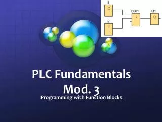
Function Block Diagram • A block in LOGO! is a function which converts the input information to output information. • Here S1 & S2 are the terminals that are connected to the AND function block. • The output H1 will be ON only if both the switches S1 and S2 are ON.
3.4 LOGO! Soft Overview • LOGO!Soft Comfortis a programming software for the LOGO • Using LOGO!Soft, you can create control programs and transfer them to LOGO! • The LOGO!Soft user interface has the following function areas as shown in figure 3.5 below: • Menu bar • Standard tool bar • Programming Interface • Info box • Status Bar • Toolbox • Constants, connectors, functions
3.4 LOGO! Soft Overview • LOGO! provides various elements in programming mode. • Co: Connector List. • GF: List of basic functions AND, OR, and so on. • SF: List of special functions. • The Co, GF and SF tabs could be used to select the terminals and function blocks.
Creation of a control program using Function Blocks • The following program demonstrates the OR function. • The input and output terminals and the OR function are used to create the function block diagram.
The following rules must be followed while connecting the blocks: • Connection can be made between one block output and one block input. • An output can be connected to several inputs. • An input cannot be connected to several outputs.
Program Simulation • The program can be tested using simulation. A program is tested by specifying the input signals and observing desired output signal as shown in figure. The red lines carry a 1-signal and the blue lines carry a 0-signal.
Program Transfer to LOGO! • The program can be downloaded from the PC to LOGO! and then tested.
3.5 Memory function • Memory function is used to store a signal. • It has SET (S) and RESET (R) inputs. • A high at the set input sets (stores 1) the memory function, and a high at the reset input resets the memory function.
3.6 Timing function • This function is used to provide a time-delay in a circuit. • In the figure, a switch-off delay is used to delay the off-time. The lamp P1 will be off after 5 seconds.
The Figure shows the timing function block. • T input is used to set the time. • The Q output will be high for the time set at the T input.
Timer Types • There are different types of timers: • OFF Delay timer: It is used when there is a need to stop an action after a certain time. • ON Delay timer: It is used to start an action after a certain time. • For example, some machines do not require running immediately when switched on, but after a certain time, either for safety or for lubrication.
3.7 Counting function • Counting functions are used to detect the number of items and events. • For example, a counter may be required to count exactly 10 identical parts that need to be fed onto a conveyor of the sorting system. • The Figure shows the counter function block.: • PV is the Preset Value. • The counter value increases by 1 for each input signal at CU. • When the preset value is reached. • the output Q becomes ‘1’.
3.8 Summary of Basic Control Functions • The Basic Control Functions include the following: • Logic functions (AND,OR,NOT) • Memory functions (Latching) • Timing Functions. • Counting Functions.
Class Activities • Skill 1 • Skill 2 • 3.12 Review Exercise