Download
1 / 1
10 likes | 182 Vues
P09233 2008-3 & 4. Airframe Measurements Group Measurements Box. Special Thanks to. &. Project Background:

E N D
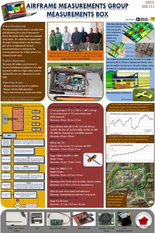
P09233 2008-3 & 4 Airframe Measurements Group Measurements Box Special Thanks to & • Project Background: • The long term goal of this project is to create, field and implement a full system of measurement devices that will be used to control an unmanned aerial vehicle. This will be the first quarter that the project is being worked on, and the primary goal will be to implement off the shelf measurement devices to characterize the necessary parameters for in-flight control of an unmanned aerial vehicle. • Problem Statement: • The project will combine several sensors to measure the fundamental parameters of in-flight movement to allow for a flight control system to calculated the necessary information to sustain flight. • Objectives/Scope: • - Measure real time position of test platform • - Measure real time flight parameters • Ensure measurements are accurate and reliable • Visit our wed page for more information and documentation: • https://edge.rit.edu/content/P09233/public/Home Group Members Michael Skube (ME), James Hunt (ME), Joseph Peters (EE), Bill Atkinson (ME), John Isely (ME), Heidi Morgan (EE), Kevin Li (EE) Faculty Advisor: Dr Jason Kolodziej Pitot Static Tube Mounting and sensor mounted in the wing tip, both can be removed and replaced without complete wing disassembly. Pitot Tube Pitot Tube Mount Velocity Sensor The completed measurements box fits inside the fuselage of Airframe A (P09231). The box is attached with 4 thumb screws, and the complete box also acts as the outer fuselage, sealing the hole that is required to insert the box into the airframe. Complete Measurements “BOX” Measurement Box in Airframe A Box inside Airframe A The Pitot Static Tube was compared against a anemometer, measuring the velocity of a automobile, the accuracy is reasonable given the low cost of the Pitot Static tube setup. Sensor and MCU Integration • Inertial Measurement Unit “IMU”(Analog Devices ADIS16350) • - Tri-axis gyroscope ± 75°/s, ± 150°/s, ± 300°/s settings • - Tri-axis accelerometer ± 10 g measurement range • - 350 Hz bandwidth • - Dimensions: 23 mm x 23 mm x 23 mm • Microcontroller (AT91SAM7S256) • Flash, 64K Bytes RAM, USB 2.0, RTT, 10 bit ADC 384 ksps • 2x UARTs, TWI (I2C), SPI, 3x 32bit TIMERS, 4x PWM, SSC, WDT • PDC (DMA) for all peripherals, up to 60MHz operation • - Dimensions: 80 mm x 120 mm • GPS (San Jose Navigation) • - Refresh rate: 5 Hz • - Accuracy: 3.3 m accuracy, 2.6 m accuracy with DGPS • - Dimensions: 2.6 cm x 2.6 cm x 0.6 cm • Airspeed (Eagle Tree Airspeed Micro Sensor) • - Range: 2 MPH to 350 MPH ± 1 MPH • - Weight: 7 Grams • - Dimensions: 28 mm x 16 mm x 10 mm • Altimeter (Zlog) • - Range: 0 to 10000 ft ± 1 ft • - Weight: 8 Grams • - Dimensions: 40 mm x 23.4 mm x 9.4 mm • Measurement Box Design • - Mounting positions for all sensors & includes vibration isolation • - Dimension: 3 in x 3.25 in x 3.75 in w/t base plate 6 in • Pitot Tube Mounting Design • Allows for quick sensor removal and replacement • Dimension: Contained between outermost 2 wing tip ribs • Ultrasonic Sensor (Maxbotix LV-EZ0) • - Range: 0 to 255 inches • - Dimensions: 21.1 mm x 19.9 mm x 16.4 mm The altimeters where tested against a calibrated pressure sensor to show their accuracy, based on repeatability and accuracy, the ZLOG altimeter was chosen. GPS data was collected on a drive around the outer loop of RIT to shows it’s accuracy. IMU Eagle Tree Velocity Sensor GPS Zlog Altitude Sensor Microcontroller Ultrasonic Altitude Sensor Inertia Measurement Unit