Download
1 / 44
440 likes | 546 Vues
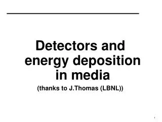
Detectors and energy deposition in media (thanks to J.Thomas (LBNL)). ATLAS vs PHENIX vs …. They are about the same size They are about the same shape Are they really different?. ATLAS. Even fixed target detectors look like an angular slice of one of these detectors. PHENIX. References.

E N D
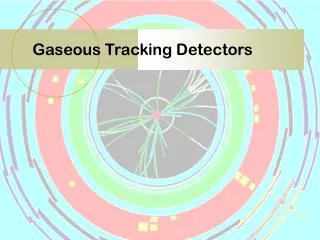
Detectors and energy deposition in media (thanks to J.Thomas (LBNL))
ATLAS vs PHENIX vs …. They are about the same size They are about the same shape Are they really different? ATLAS Even fixed target detectors look like an angular slice of one of these detectors PHENIX
References Outstanding References • Particle Properties Data Booklet • Particle properties • Excellent summaries of particle detection techniques • http://pdg.lbl.gov to view the pages or order your own copy • Sauli’s lecture notes on wire chambers (CERN 77-09) • W. Blum and L. Rolandi, “Particle Detection with Drift Chambers”, Springer, 1994. This talk relies heavily on additional resources from the Web • C. Joram – CERN Summer Student Lectures 2003 • T.S. Verdee – SUSSP 2003 • S. Stapnes – CERN School of Phyics 2002
retina The Oldest Particle Detector – and a good one, too. • High sensitivity to photons • Good spatial resolution • Large dynamic range 1:1014 • (Once upon a time) Used to tune cyclotron beams via scintillation light
J. Plücker 1858 J.J. Thomson 1897 Thomson’s cathode ray tube manipulation By E or B field detector accelerator What should a particle detector do? • Note the scale pasted on the outside of the tube! • Glass scintillates and we “see” the effect on the electron beam • Today … mean pt is 500 MeV so we need a meter of steel and concrete to stop the particle and make a total energy measurement.
First electrical signal from a particle E. Rutherford 1909 H. Geiger pulse The Geiger counter
First tracking detector C. T. R. Wilson, 1912, Cloud chamber The general procedure was to allow water to evaporate in an enclosed container to the point of saturation and then lower the pressure, producing a super-saturated volume of air. Then the passage of a charged particle would condense the vapor into tiny droplets, producing a visible trail marking the particle's path.
Detector Philosophy • Particles are detected by their interaction with matter • Many different physical principals are involved • Electromagnetic • Weak • Strong • Gravity • Most detection techniques rely on the EM interaction • Although, all four fundamental forces are used to measure and detect particles • Ultimately, we observe ionization and excitation of matter. In this day and age, it always ends up as an electronic signal.
Interaction of Charges Particles with Matter Coulomb Scattering An incoming particle with charge z interacts with a target of nuclear charge Z. The cross-section for this e.m. process is Average scattering angle < θ > = 0 Cross-section for θ→ 0 is infinite ! This implies that there will be many soft scattering events. Multiple Coulomb Scattering In sufficiently thick material layer the particle will undergo multiple scattering. There will be angular deflections and energy loss. Rutherford formula Radiation Length
q e - How do particles lose energy in matter? “kinematic term” “minimum ionizing particles” 3-4 “relativistic rise” density effect Bethe-Bloch Formula ionization constant
dE/dx depends on b • dE/dx depends only on b and isindependent of mass • Particles with different masses have different momenta (for same ) • dE/dx in [MeV g-1cm2] • in a gas detector this gets shortened to keV/cm. • First approximation: medium characterized by electron density, N ~ Z/A. Pep 4 TPC
e- <DE> e- DE Landau tails Real detectors (limited granularity) can not measure <dE/dx> . They measure the energy DE deposited in a layer of finite thickness dx. For thin layers Few collisions, some with high energy transfer. Energy loss distributions show large fluctuations towards high losses: ”Landau tails” due to “d electrons” DE <DE> For thick layers and high density materials Many collisions Central Limit Theorem Gaussian shape distributions.
Ionization of gases Fast charged particles ionize the atoms of a gas. Often the resulting primary electron will have enough kinetic energy to ionize other atoms. Primary ionization Total ionization 10 - 40 pairs/cm DE/pair ~ 25 eV Assume detector, 1 cm thick, filled with Ar gas: 1 cm ~ 100 e-ion pairs 100 electron-ion pairs are not easy to detect! Noise of amplifier 1000 e- (ENC) ! We need to increase the number of e-ion pairs.
Gas Amplification in a Proportional Counter Consider cylindrical field geometry (simplest case): C = capacitance / unit length Electrons drift towards the anode wire Close to the anode wire the electric field is sufficiently high (kV/cm), that the e- gain enough energy for further ionization exponential increase in the number of e--ion pairs.
Signal Formation - Proportional Counter (F. Sauli, CERN 77-09) Avalanche form within a few radii or the wire and within t < 1 ns! Signal induction both on anode and cathode due to moving charges (both electrons and ions). Electrons are collected on the anode wire, (i.e. dr is small, only a few mm). Electrons contribute only very little to detected signal (few %). (F. Sauli, CERN 77-09) Ions have to drift back to cathode, i.e. dr is big. Signal duration limited by total ion drift time ! We need electronic signal differentiation to limit dead time.
field lines and equipotentials around anode wires Multiwire Proportional Chamber Multi wire proportional chamber(MWPC) (G. Charpak et al. 1968, Nobel prize 1992) Address of fired wire(s) only give 1-dimensional information. This is sometimes called “Projective Geometry”. It would be better to have a second dimension …. Typical parameters: L = 5mm, d = 1mm, rwire= 20mm. Normally digital readout: spatial resolution limited to ( d=1mm, sx=300 mm )
The Second Dimension … 2D readout Crossed wire planes. Ghost hits. Restricted to low multiplicities. 90 degrees or stereo planes crossing at small angle. Charge division: Resistive wires (Carbon,2k/m). Timing difference: Segmented cathode planes: Analog readout of cathode planes s 100 mm
x Measure arrival time of electrons at sense wire relative to a time t0. Timing Difference: Drift Chambers Drift Chambers : • Reduced numbers of readout channels • Distance between wires typically 5-10cm giving around 1-2 s drift-time • Resolution of 50-100m achieved limited by field uniformity and diffusion • Perhaps problems with occupancy of tracks in one cell. (First studies: T. Bressani, G. Charpak, D. Rahm, C. Zupancic, 1969 First operation drift chamber: A.H. Walenta, J. Heintze, B. Schürlein, NIM 92 (1971) 373)
42mm 13 mm Wire Electrode Strip Mylar Drift Chambers: Many Possible Designs • What happens during the drift towards the anode wire? • We need to know the drift velocity • Diffusion, too. (U. Becker, in: Instrumentation in High Energy Physics, World Scientific)
Drift and Diffussion in Gases Without external fields: Electrons and ions will lose their energy due to collisions with the gas atoms thermalization Undergoing multiple collisions, a localized ensemble of charges will diffuse D: diffusion coefficient With External electric field: multiple collisions due to scattering from gas atoms drift Typical electron drift velocity:5 cm/ms Ion drift velocities are ~1000 times smaller
3D: The Time Projection Chamber STAR TPC Time Projection Chamberfull 3-D track reconstruction • x-y from wires and segmented cathode of MWPC • z from drift time • in addition dE/dx information Diffusion significantly reduced by B-field. Requires precise knowledge of vD LASER calibration + p,T corrections Drift over long distances very good gas quality required Gate closed Gate open Space charge problem from positive ions, drifting back to midwall use a gated grid ALEPH TPC (ALEPH coll., NIM A 294 (1990) 121, W. Atwood et. Al, NIM A 306 (1991) 446) Ø 3.6M, L=4.4 m sRf = 173 mm sz = 740 mm (isolated leptons) DVg = 150 V
Momentum Measurement in a Uniform Field The sagitta is determined by 3 measurements with error s(x): ( N > 10 )
Momentum Resolution: the STAR Magnet + TPC MCS Contribution • Momentum resolution is only limited by the strength of the magnetic field and is independent of the mass of the particle at high PT • Momentum resolution at low PT is determined by multiple coulomb scattering (MCS) B Field limited
p+ implant Si (n type) n+ implant Semiconductor Detectors: Silicon The typical Semiconductor detector is a based on a Si diode structure Interaction with ionizing radiation Reading out the pixels
The Properties of Silicon • Si Structures are small and can be mass produced in large arrays • Ideal for locating a point on the track of a particle
Scintillation Light: Inorganic Scintillators PbWO4 ingot and final polished CMS ECAL scintillator crystal from Bogoroditsk Techno-Chemical Plant (Russia).
Inorganic Scintillators: NaI, BGO, PbWO4, … • Excitation of electrons into the conduction band allows light to be produced during relaxation to the ground state. • Inorganic scintillators are usually high density and high Z materials • Thus they can stop ionizing radiation in a short distance
Scintillation Light: Organic Scintillators • Liquid and plastic organic scintillators are available • They normally consist of a solvent plus secondary (and tertiary) fluors as wavelength shifters.
adiabatic Scintillator Readout Schemes Geometrical adaptation: Light guides: transfer by total internal reflection (+outer reflector) Wavelength shifter (WLS) bars “fish tail” PhotoDetector
photon e- Photo Multiplier Tubes (PMT) (Philips Photonic) • Main phenomena: • photo emission from photo cathode. • secondary emission from dynodes. • dynode gain g = 3-50 (f(E)) • total gain • 10 dynodes with g=4 • M = 410 106
Scintillator Applications Tracking Charged particle passing through a stack of scintillating fibers (diam. 1mm) Sampling Calorimeters Absorber + detector separated additional sampling fluctuations Time of Flight Measure the time of flight of a particle between a thin, flat, “start” counter and a thin “stop” counter.
Measurement of Energy: Calorimeters Big European Bubble Chamber filled with Ne:H2 = 70%:30% 3T field, L=3.5m, X0=34 cm 50 GeV incident electron
150 GeV Pion Showers in Cu Hadron shower not as well behaved as an em one Hadron calorimeter are always sampling calorimeters
Lets Design a Detector: Requirements Very good particle identification trigger efficiently and measure ID and momentum of all particles High resolution electromagnetic calorimetry Powerful inner tracking systems Improves momentum resolution, find tracks of short lived particles Hermetic coverage good rapidity coverage, good missing ET resolution Affordable detector
Time Projection Chamber Magnet Coils Silicon Tracker SVT & SSD TPC Endcap & MWPC FTPCs Endcap Calorimeter Beam Beam Counters Barrel EM Calorimeter Central Trigger Barrel & TOF The STAR Detector at RHIC Not Shown: pVPDs, ZDCs, PMD, and FPDs
Conclusions • We have taken a random walk through a variety of detector technologies and put the pieces together into a detector • You can repeat this exercise using the PDG booklet (!) • It contains a wealth of information • It is extremely well written and only contains the most essential information • The design of HENP detectors is driven by the desire to measure the ID and momentum of all particles in the range from 100 MeV to 100 GeV. • all 4 components of the momentum 4-vector (E, px, py, pz) • all 4 components of the spacial 4-vector (ct, x, y, z) • If you can afford to do this with full 4p coverage, then your detector will end up looking pretty much like all the other big detectors. However, there are big differences in the details and cost effectiveness of each detector design.
STAR Solenoidal field Large Solid Angle Tracking TPC’s, Si-Vertex Tracking RICH, EM Cal, TOF PHENIX Axial Field High Resolution & Rates 2 Central Arms, 2 Forward Arms TEC, RICH, EM Cal, Si, TOF, -ID Measurements of Hadronic observables using a large acceptance spectrometer Event-by-event analyses of global observables, hadronic spectra and jets Leptons, Photons, and Hadrons in selected solid angles (especially muons) Simultaneous detection of phase transition phenomena (e–m coincidences) Two “Large” Detectors at RHIC
BRAHMS 2 Spectrometers - fixed target geometry Magnets, Tracking Chambers, TOF, RICH PHOBOS “Table-top” 2 Arm Spectrometer Magnet, Si -Strips, Si Multiplicity Rings, TOF Paddle Trigger Counter TOF Spectrometer Octagon+Vertex Ring Counters Inclusive particle production over a large rapidity and pt range Low pt charged hadrons Multiplicity in 4 & Particle Correlations Two “Small” Experiments at RHIC