Torsion
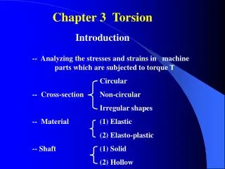
3. Torsion. Contents. Statically Indeterminate Shafts Sample Problem 3.4 Design of Transmission Shafts Stress Concentrations Plastic Deformations Elastoplastic Materials Residual Stresses Example 3.08/3.09 Torsion of Noncircular Members Thin-Walled Hollow Shafts Example 3.10.

Torsion
E N D
Presentation Transcript
3 Torsion
Contents Statically Indeterminate Shafts Sample Problem 3.4 Design of Transmission Shafts Stress Concentrations Plastic Deformations Elastoplastic Materials Residual Stresses Example 3.08/3.09 Torsion of Noncircular Members Thin-Walled Hollow Shafts Example 3.10 Introduction Torsional Loads on Circular Shafts Net Torque Due to Internal Stresses Axial Shear Components Shaft Deformations Shearing Strain Stresses in Elastic Range Normal Stresses Torsional Failure Modes Sample Problem 3.1 Angle of Twist in Elastic Range
Torsional Loads on Circular Shafts • Interested in stresses and strains of circular shafts subjected to twisting couples or torques • Turbine exerts torque T on the shaft • Shaft transmits the torque to the generator • Generator creates an equal and opposite torque T’
Net of the internal shearing stresses is an internal torque, equal and opposite to the applied torque, Net Torque Due to Internal Stresses • Although the net torque due to the shearing stresses is known, the distribution of the stresses is not • Distribution of shearing stresses is statically indeterminate – must consider shaft deformations • Unlike the normal stress due to axial loads, the distribution of shearing stresses due to torsional loads can not be assumed uniform.
The existence of the axial shear components is demonstrated by considering a shaft made up of axial slats.The slats slide with respect to each other when equal and opposite torques are applied to the ends of the shaft. Axial Shear Components • Torque applied to shaft produces shearing stresses on the faces perpendicular to the axis. • Conditions of equilibrium require the existence of equal stresses on the faces of the two planes containing the axis of the shaft
From observation, the angle of twist of the shaft is proportional to the applied torque and to the shaft length. • When subjected to torsion, every cross-section of a circular shaft remains plane and undistorted. • Cross-sections of noncircular (non-axisymmetric) shafts are distorted when subjected to torsion. Shaft Deformations • Cross-sections for hollow and solid circular shafts remain plain and undistorted because a circular shaft is axisymmetric.
It follows that • Shear strain is proportional to twist and radius Shearing Strain • Consider an interior section of the shaft. As a torsional load is applied, an element on the interior cylinder deforms into a rhombus. • Since the ends of the element remain planar, the shear strain is equal to angle of twist.
Multiplying the previous equation by the shear modulus, From Hooke’s Law, , so The shearing stress varies linearly with the radial position in the section. • Recall that the sum of the moments from the internal stress distribution is equal to the torque on the shaft at the section, • The results are known as the elastic torsion formulas, Stresses in Elastic Range
Elements with faces parallel and perpendicular to the shaft axis are subjected to shear stresses only. Normal stresses, shearing stresses or a combination of both may be found for other orientations. • Consider an element at 45o to the shaft axis, • Element a is in pure shear. Normal Stresses • Element c is subjected to a tensile stress on two faces and compressive stress on the other two. • Note that all stresses for elements a and c have the same magnitude
Ductile materials generally fail in shear. Brittle materials are weaker in tension than shear. • When subjected to torsion, a ductile specimen breaks along a plane of maximum shear, i.e., a plane perpendicular to the shaft axis. • When subjected to torsion, a brittle specimen breaks along planes perpendicular to the direction in which tension is a maximum, i.e., along surfaces at 45o to the shaft axis. Torsional Failure Modes
Sample Problem 3.1 • SOLUTION: • Cut sections through shafts AB and BC and perform static equilibrium analysis to find torque loadings • Apply elastic torsion formulas to find minimum and maximum stress on shaft BC Shaft BC is hollow with inner and outer diameters of 90 mm and 120 mm, respectively. Shafts AB and CD are solid of diameter d. For the loading shown, determine (a) the minimum and maximum shearing stress in shaft BC, (b) the required diameter d of shafts AB and CD if the allowable shearing stress in these shafts is 65 MPa. • Given allowable shearing stress and applied torque, invert the elastic torsion formula to find the required diameter
Sample Problem 3.1 • SOLUTION: • Cut sections through shafts AB and BC and perform static equilibrium analysis to find torque loadings
Given allowable shearing stress and applied torque, invert the elastic torsion formula to find the required diameter • Apply elastic torsion formulas to find minimum and maximum stress on shaft BC Sample Problem 3.1
Recall that the angle of twist and maximum shearing strain are related, • In the elastic range, the shearing strain and shear are related by Hooke’s Law, • Equating the expressions for shearing strain and solving for the angle of twist, • If the torsional loading or shaft cross-section changes along the length, the angle of rotation is found as the sum of segment rotations Angle of Twist in Elastic Range
From a free-body analysis of the shaft,which is not sufficient to find the end torques. The problem is statically indeterminate. • Divide the shaft into two components which must have compatible deformations, • Substitute into the original equilibrium equation, Statically Indeterminate Shafts • Given the shaft dimensions and the applied torque, we would like to find the torque reactions at A and B.
Sample Problem 3.4 • SOLUTION: • Apply a static equilibrium analysis on the two shafts to find a relationship between TCD and T0 • Apply a kinematic analysis to relate the angular rotations of the gears • Find the maximum allowable torque on each shaft – choose the smallest Two solid steel shafts are connected by gears. Knowing that for each shaft G = 11.2 x 10⁶ psi and that the allowable shearing stress is 8 ksi, determine (a) the largest torque T0 that may be applied to the end of shaft AB, (b) the corresponding angle through which end A of shaft AB rotates. • Find the corresponding angle of twist for each shaft and the net angular rotation of end A
SOLUTION: • Apply a static equilibrium analysis on the two shafts to find a relationship between TCD and T0 • Apply a kinematic analysis to relate the angular rotations of the gears Sample Problem 3.4
Find the T0 for the maximum allowable torque on each shaft – choose the smallest • Find the corresponding angle of twist for each shaft and the net angular rotation of end A Sample Problem 3.4
Determine torque applied to shaft at specified power and speed, • Find shaft cross-section which will not exceed the maximum allowable shearing stress, Design of Transmission Shafts • Principal transmission shaft performance specifications are: • power • speed • Designer must select shaft material and cross-section to meet performance specifications without exceeding allowable shearing stress.
The derivation of the torsion formula,assumed a circular shaft with uniform cross-section loaded through rigid end plates. • Experimental or numerically determined concentration factors are applied as Stress Concentrations • The use of flange couplings, gears and pulleys attached to shafts by keys in keyways, and cross-section discontinuities can cause stress concentrations
With the assumption of a linearly elastic material, • The integral of the moments from the internal stress distribution is equal to the torque on the shaft at the section, Plastic Deformations • If the yield strength is exceeded or the material has a nonlinear shearing-stress-strain curve, this expression does not hold. • Shearing strain varies linearly regardless of material properties. Application of shearing-stress-strain curve allows determination of stress distribution.
At the maximum elastic torque, • As the torque is increased, a plastic region ( ) develops around an elastic core ( ) • As , the torque approaches a limiting value, Elastoplastic Materials
On a T-f curve, the shaft unloads along a straight line to an angle greater than zero • Residual stresses found from principle of superposition Residual Stresses • Plastic region develops in a shaft when subjected to a large enough torque • When the torque is removed, the reduction of stress and strain at each point takes place along a straight line to a generally non-zero residual stress
A solid circular shaft is subjected to a torque at each end. Assuming that the shaft is made of an elastoplastic material with and determine (a) the radius of the elastic core, (b) the angle of twist of the shaft. When the torque is removed, determine (c) the permanent twist, (d) the distribution of residual stresses. Example 3.08/3.09 • SOLUTION: • Solve Eq. (3.32) for rY/c and evaluate the elastic core radius • Solve Eq. (3.36) for the angle of twist • Evaluate Eq. (3.16) for the angle which the shaft untwists when the torque is removed. The permanent twist is the difference between the angles of twist and untwist • Find the residual stress distribution by a superposition of the stress due to twisting and untwisting the shaft
SOLUTION: • Solve Eq. (3.32) for rY/c and evaluate the elastic core radius • Solve Eq. (3.36) for the angle of twist Example 3.08/3.09
Evaluate Eq. (3.16) for the angle which the shaft untwists when the torque is removed. The permanent twist is the difference between the angles of twist and untwist • Find the residual stress distribution by a superposition of the stress due to twisting and untwisting the shaft Example 3.08/3.09
Previous torsion formulas are valid for axisymmetric or circular shafts • For uniform rectangular cross-sections, • At large values of a/b, the maximum shear stress and angle of twist for other open sections are the same as a rectangular bar. Torsion of Noncircular Members • Planar cross-sections of noncircular shafts do not remain planar and stress and strain distribution do not vary linearly
Summing forces in the x-direction on AB, • shear stress varies inversely with thickness • Compute the shaft torque from the integral of the moments due to shear stress • Angle of twist (from Chapt 11) Thin-Walled Hollow Shafts
Example 3.10 Extruded aluminum tubing with a rectangular cross-section has a torque loading of 24 kip-in. Determine the shearing stress in each of the four walls with (a) uniform wall thickness of 0.160 in. and wall thicknesses of (b) 0.120 in. on AB and CD and 0.200 in. on CD and BD. • SOLUTION: • Determine the shear flow through the tubing walls • Find the corresponding shearing stress with each wall thickness
SOLUTION: • Determine the shear flow through the tubing walls • Find the corresponding shearing stress with each wall thickness • with a uniform wall thickness, with a variable wall thickness Example 3.10