Torsion
Torsion. Torsional Deformation of a circular shaft, Torsion Formula , Power Transmission. Torsional Deformation of a circular shaft . Length BD. when. The Torsion Formula . Angular strain is proptional to shear stress: . Mean:

Torsion
E N D
Presentation Transcript
Torsion Torsional Deformation of a circular shaft, Torsion Formula , Power Transmission
Torsional Deformation of a circular shaft Length BD when
The Torsion Formula Angular strain is proptional to shear stress: • Mean: • highest shear stress: will be at farthest away from center • At the center point, there will be no angular strain and therefore no shear stress is developed.
The Torsion Formula J: Polar moment of area Maximum shear stress due to torsion Shear stress due to torsion at radius r
Polar Moment of Inertia Polar Moment of Inertia (J) Solid shaft Tubular shaft
Solve it! The solid circular shaft is subjected to an internal torque of T= 5kNm. Determine the shear stress developed at point A and B. Represent each state of stress on a volume of element.
Solve it! The solid circular shaft is subjected to an internal torque of T= 5kNm. Determine the shear stress developed at point A and B. Represent each state of stress on a volume of element.
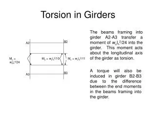
Example 1 The shaft shown in figure is supported by two bearings and is subjected to three torques. Determine the shear stress developed at points A and B, located at section a-a of the shaft.
Point A R = 0.075 m J = Jtotal T = internal torque Point B R = 0.015 m J = Jtotal T = internal torque T=4.25 – 3.0 = 1.25 kNm
Solve it! Determine the maximum shear stress developed in the shaft at section a-a.
Maximum Torsional Shear T:2100 Nm = 2100(10)3 Nmm r: 40 mm J: tubular Polar Moment of Area Max torsional shear when r = 40mm
Solve it! The solid shaft has a diameter of 40 mm. Determine the absolute maximum shear stress in the shaft.
Maximum Torsional Shear T:70 Nm = 70(10)3 Nmm r: 20 mm J: solid r =20 mm
Power Transmission Power P: power (1 Watt = 1 Nm/s) T: torque (Nm) w: radian/s Input n(rpm) Input frequency of shaft rotation
Solve it ! The gear motor can develop 1.6kW when it turns at 450 rev/min. If the shaft has a diameter of 25mm, determine the maximum shear stress developed in the shaft.
Calculate the T Maximum shear stress
Solve it ! The gear motor can develop 2.4kW when it turns at 150 rev/min. If the allowable shear stress for the shaft is tallow = 84 Mpa, determine the smallest of the shaft to nearest multiples of 5mm that can be used.
Solve it ! Calculate the T Maximum shear stress Calculate d
Lecture 1 Angle Twist
Lecture 1 Right hand rule Sign Convention +ve: direction of the thumb is away from the part
Solve it! The splined ends and gears attached to the A-36 steel shaft are subjected to the torques shown. Determine the angle of twist of end B with respect to end A. The shaft has a diameter of 40 mm.
300Nm 400Nm 500Nm 200Nm 300Nm Tac= 300Nm 500Nm Tcd=200Nm 300Nm Tdb =400Nm 400Nm Total angle of twist:
Solve it ! The two shafts are made of A-36 steel. Each has a diameter of 25mm, and they are supported by bearings at A, B and C, which allow free rotation. If the support at D is fixed, determine of the angle of twist of end B and A when the toques are applied to the assembly as shown.
Direction of FF Equilibrium of shaft AGFB FF Equilibrium at gear F and E Direction of FE FE
Direction of FF Equilibrium of shaft DCE 9ONm 3ONm 12ONm FE 3ONm 3ONm 9ONm 9ONm
Length of arc 12 = length of 13 3 2 1 Angle of twist at end B = angle of twist at F FB : there is no torque Angle of twist at end A