Download
1 / 21
220 likes | 433 Vues
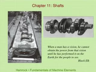
Chapter 11: Shafts. When a man has a vision, he cannot obtain the power from that vision until he has performed it on the Earth for the people to see. Black Elk. Shaft Design Procedure.

E N D
Chapter 11: Shafts When a man has a vision, he cannot obtain the power from that vision until he has performed it on the Earth for the people to see. Black Elk
Shaft Design Procedure 1. Develop a free-body diagram by replacing the various machine elements mounted on the shaft by their statically equivalent load or torque components. To illustrate this, Fig. 11.1(a) shows two gears exerting forces on a shaft, and Fig. 11.1(b) then shows a free-body diagram of the gears acting on the shaft. 2. Draw a bending moment diagram in the x-y and x-z planes as shown in Fig. 11.1(c). The resultant internal moment at any section along the shaft may be expressed as 3. Develop a torque diagram as shown in Fig. 11.1(d). Torque developed from one power-transmitting element must balance the torque from other power-transmitting elements. 4. Establish the location of the critical cross-section, or the x location where the torque and moment are the largest. 5. For ductile materials use the maximum-shear-stress theory (MSST) or the distortion-energy theory (DET) covered in Sec. 6.7.1. 6. For brittle materials use the maximum-normal-stress theory (MNST), the internal friction theory (IFT), or the modified Mohr theory (MMT), covered in Sec. 6.7.2.
Shaft Assembly Figure 11.1 Shaft assembly. (a) Shaft with two bearings at A and B and two gears with resulting forces P1 and P2; (b) free-body diagram of torque and forces resulting from assembly drawing; (c) moment diagram in xz and xy planes; (d) torque diagram.
Example 11.1 Figure 11.2 Illustration for Example 11.1. (a) Chain drive assembly; (b) free-body diagram; (c) bending moment diagram.
Example 11.2 Figure 11.3 Illustration for Example 11.2. (a) Assembly drawing; (b) free-body diagram; (c) moment diagram in xz plane; (d) moment diagram in xy plane; (e) torque diagram.
Fluctuating Stresses on Shafts Figure 11.5 Soderberg line for shear stresses. Figure 11.4 Fluctuating normal and shear stresses acting on shaft. (a) Stresses acting on rectangular element; (b) stresses acting on oblique plane at angle ϕ.
Derivation in Eq. (11.29) Figure 11.6 Illustration of relationship given in Eq. (11.29).
Shaft Design Equations Using DET and Soderberg Criteria
Example 11.4 Figure 11.7 Section of shaft in Example 11.4.
Critical Frequency of Shafts Single Mass Multiple Mass - Raleigh Equation Multiple Mass - Dunkerly Equation Figure 11.8 Simple single-mass system.
Example 11.5 Figure 11.9 Simply supported shaft arrangement for Example 11.5.
Keys and Pins Figure 11.10 Illustration of keys and pins. (a) Dimensions of shaft with keyway in shaft and hub; (b) square parallel key; (c) flat parallel key; (d) tapered key; (e) tapered key with Gib head, or Gib-head key. The Gib head assists in removal of the key; (f) round key; (g) Woodruff key with illustration of mountingl (h) pin, which is often grooved. The pin is slightly larger than the hole so that friction holds the pin in place; (i) roll pin. Elastic deformation of the pin in the smaller hole leads to friction forces that keep the pin in place.
Plain Parallel Keys Table 11.1 Dimensions of selected square plain parallel stock keys.
Tapered Keys Table 11.2 Dimensions of square and flat taper stock keys.
Woodruff Keys Table 11.3 Dimensions of selected Woodruff keys.
Set Screws Table 11.4 Holding force generated by setscrews.
Flywheel Figure 11.11 Flywheel with driving (mean) torque Tm and load torque Tl.
Coefficient of Fluctuation Table 11.5 Coefficient of fluctuation for various types of equipment.
Design Procedure for Sizing a Flywheel 1. Plot the load torque Tl versus θ for one cycle. 2. Determine Tl,avg over one cycle. 3. Find the locations θωmax and θωmin. 4. Determine kinetic energy by integrating the torque curve. 5. Determine ωavg. 6. Determine Im from Eq. (11.72). 7. Find the dimensions of the flywheel.
Example 11.7 Figure 11.12 Load or output torque variation for one cycle used in Example 11.7.
Materials for Flywheels Table 11.6 Materials for flywheels.