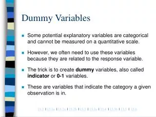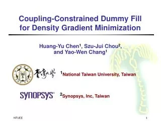
Coupling-Constrained Dummy Fill Density Analysis
150 likes | 193 Vues
This research introduces a novel algorithm for dummy fill density analysis while considering coupling constraints for optimal layout density control. The algorithm aims to identify feasible locations for dummy fills with minimal coupling violations. By emphasizing ground fills and maximizing floating fill insertion, it offers an effective solution for improving layout density uniformity. Experimental results demonstrate the algorithm's efficiency in resolving coupling issues compared to traditional methods.

Coupling-Constrained Dummy Fill Density Analysis
E N D
Presentation Transcript
Dummy Fill Density Analysis with Coupling Constraints Hua Xiang*, Liang Deng+, Ruchir Puri*, Kai-Yuan Chao‡, and Martin D.F. Wong+ *IBM T.J. Watson Research Center +Univ. of Illinois at Urbana-Champaign ‡Intel Corporation
Dummy Fill Density Analysis with Coupling Constraints • Two phases for layout density control • Density Analysis Decide available positions for fills • Fill Synthesis Determine the amount of dummy fills for each density window • Most literature works focus on fill synthesis • Different fill positions have different coupling impacts on neighboring wires. Test Structure Floating fills can lead to 3%~10% capacitance increase.
Coupling constrained Dummy Fill Analysis (CDF) • Given a given routing solution with N signal wires, each wire has a coupling threshold. • Identify fill positions such that • Min-spacing (wire-dummy, dummy-dummy) is satisfied • The total coupling capacitance on each wire does not exceed the given threshold • Target: • Find as many as possible feasible locations for ground fills • Maximize floating fill insertion
Algorithm Outline CDF Algorithm 1. Build the capacitive coupling lookup table. 2. Slice the layout into slots. 3. Partition slots into dummy fill regions. 4. Identify feasible dummy fill areas for each region. 5. Determine ground/floating fill locations
Dummy Fill Region • Slot Partition • Case A: No feasible positions between two wires • Case B: No coupling constraints on the wire • Case C: Large spacing between two wires • Optimal dummy fill regions
Optimal Dummy Fill Regions • ILP formulation
Dummy Fill Regions • To maximize dummy fill region generation, not all slots can get dummy assigned. • If no fills are inserted in a slot, the spacing between two wires is large and it is desirable to insert dummies for density uniformity.
Optimal Dummy Fill Insertion • ILP formulation
Ground Fills • Ground fills are more robust and predictable. So they are still favored over floating fills. • Ground fills have to reach power rails on upper/lower layers.
Ground Fills & Floating Fills • Ground fill positions affect floating fill insertion.
Fill Position Calculation • Maximize and decide ground fill positions first. • Determine floating fills after ground fills are settled. • Dynamic programming based algorithm 1) Identify ground fill regions Gi 2) Scan the ground fill regions from bottom to top a) Check each position Pi in Gi b) Calculate the maximum floating fills below Pi 3) Get the maximum number of floating fills 4) Trace back to determine fill positions
Fill Position Calculation (Cont) • Ground fill region scan • Floating fill calculation
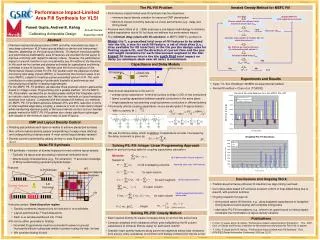
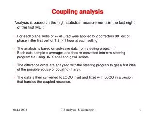
Experiment Results • Implemented in C on a linux workstation (2.3GHz) • Test cases are derived from industry designs
Experiment Results (Cont) • Compared with fill insertion algorithm without considering coupling constraints, as denoted as “NoCap”. • NoCap leads to a large number of coupling violations. • The max/ave density of CDF and NoCap is pretty close, which means that CDF can effectively identify feasible locations. • The (max/ave) density difference between CDF and NoCap is due to wire patterns and coupling constraints.
Conclusion • The first dummy fill density analysis algorithm, which takes coupling constraints into consideration, is presented. • The algorithm also makes efforts to maximize ground fills, which are more predictable and robust. • The output of the algorithm can be easily adopted in density models to guide dummy fill insertion. • The output outlines dummy fill regions so that different fill patterns can be applied.