Download
1 / 39
400 likes | 433 Vues
Explore the fundamentals of MEF 6 and MEF 10 specifications for Carrier Ethernet services, including service types, attributes, and parameters. Discover how these standards shape Ethernet offerings for effective network planning.

E N D
Introducing the Specifications of the Metro Ethernet Forum February 2008
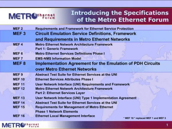
Introducing the Specifications of the Metro Ethernet Forum MEF 2 Requirements and Framework for Ethernet Service Protection MEF 3 Circuit Emulation Service Definitions, Framework and Requirements in Metro Ethernet Networks MEF 4 Metro Ethernet Network Architecture Framework Part 1: Generic Framework MEF 6 Metro Ethernet Services Definitions Phase I MEF 7 EMS-NMS Information Model MEF 8 Implementation Agreement for the Emulation of PDH Circuits over Metro Ethernet Networks MEF 9 Abstract Test Suite for Ethernet Services at the UNI MEF 10 Ethernet Services Attributes Phase I MEF 11 User Network Interface (UNI) Requirements and Framework MEF 12 Metro Ethernet Network Architecture Framework Part 2: Ethernet Services Layer MEF 13 User Network Interface (UNI) Type 1 Implementation Agreement MEF 14 Abstract Test Suite for Traffic Management Phase 1 MEF 15 Requirements for Management of Metro Ethernet Phase 1 Network Elements MEF 16 Ethernet Local Management Interface * MEF 10 * replaced MEF 1 and MEF 5
Introduction • This presentation is an introduction to both MEF 6 and MEF 10 • MEF 6 defines the Ethernet service types • MEF 10 Defines the service attributes and parameters required to offer the services defined in MEF 6 Ethernet Services “Eth” Layer Service Provider 1 Metro Ethernet Network Service Provider 2 Metro Ethernet Network Subscriber Site Subscriber Site ETH UNI-N ETH UNI-N ETH UNI-C ETH UNI-N ETH UNI-N ETH UNI-C UNI: User Network Interface, UNI-C: UNI-customer side, UNI-N network side NNI: Network to Network Interface, E-NNI: External NNI; I-NNI Internal NNI
Introduction MEF 6 Ethernet Services Definitions – Phase I Purpose Defines the Ethernet Services (EPL, EVPL, E-Line, ELAN, etc) Audience All, since it provides the fundamentals required to build devices and services that deliver Carrier Ethernet. For Enterprise users it gives the background to Service Level Specifications for Carrier Ethernet Services being offered by their Service Providers and helps to plan Ethernet Services as part of their overall network. Ethernet Services Definitions – Phase I MEF 10 Purpose Defines the service attributes and parameters required to offer the services defined in MEF 6 Audience All, since it provides the fundamentals required to build devices and services that deliver Carrier Ethernet. For Enterprise users it gives the background to Service Level Specifications for Carrier Ethernet Services being offered by their Service Providers and helps to plan Ethernet Services as part of their overall network.
Contents • Services model and taxonomy • Services type definitions • Service type application examples • SLA specifications • Traffic classification • Traffic profiles • Service attributes and parameters
Ethernet Service – Basic MEF Model Concepts • Customer Equipment (CE) attaches to the Metro Ethernet Network (MEN) at the UNI • Using standard Ethernet frames. • CE can be • Router or bridge/switch -IEEE 802.1 bridge • UNI (User Network Interface) • Demarcation point between the customer and provider network • Demarcation point between host services and provider network • Standard IEEE 802.3 Ethernet PHY/MAC
Ethernet Virtual Connection (EVC) defined … Point-to-Point EVC MEN UNI UNI • An EVC is “an instance of an association of 2 or more UNIs” • EVCs help visualize the Ethernet connections • Like Frame Relay and ATM PVCs or SVCs • Cannot leak frame from one EVC to another • MEF has defined 2 EVC types • Point-to-Point MEN Multipoint-to-Multipoint EVC EVCs define the service connectivity
Service Types defined in MEF 6 Point-to-Point EVC • E-Line Service used to create • Ethernet Private Lines • Virtual Private Lines • Ethernet Internet Access • Point-to-Point upper layer services transport (IP-VPNs etc…) • E-LAN Service used to create • Multipoint L2 VPNs • Transparent LAN Service • Multicast networks CE UNI MEN CE UNI E-Line Service type Multipoint-to-Multipoint EVC UNI UNI CE CE MEN UNI CE CE UNI E-LAN Service type
Example Service using E-Line Service Type • Ethernet Private Line • Replaces a TDM Private line • Dedicated UNIs for Point-to-Point connections • Single Ethernet Virtual Connection (EVC) per UNI Point-to-Point EVC Storage SP Ethernet UNI Ethernet UNI CE MEN CE ISP POP Ethernet UNI Internet CE Ethernet UNI Ethernet Private Line using E-Line Service type
Example Service using E-Line Service Type • Ethernet Virtual Private Line • Replaces Frame Relay or ATM services • Supports Service Multiplexed UNI* • Allows single physical connection to customer premise equipment for multiple virtual connections Multiple Point-to-Point EVCs Ethernet UNI Service Multiplexed Ethernet UNI CE MEN CE CE Ethernet UNI * This is a UNI that must be configurable to support Multiple EVCs per UNI Ethernet Virtual Private Line using E-Line Service type
Example Service using E-LAN Service Type Transparent LAN Service VLANs Sales Customer Service Engineering • Transparent LAN Service (TLS) provides • Multipoint-multipoint • Intra-company Connectivity • Full transparency of control protocols (BPDUs) • New VLANs added • without coordination with provider Multipoint-to-Multipoint EVC UNI 1 UNI 2 MEN UNI 3 VLANs Engineering VLANs Sales Customer Service UNI 4 TLS makes the MEN look like a LAN VLANs Sales
Example Service using E-LAN Service Type • Ethernet Multicast • Point to multipoint for broadcast applications (Video) • Supports Service Multiplexed UNI (to deliver multiple channels) Point-to-multipoint EVCs Ethernet UNI Service Multiplexed Ethernet UNI CE CE CE Ethernet UNI MEN Ethernet Delivery of Multicast IPTV Traffic
Ethernet Frame handling • MEF 10 Defines how the services should handle customer generated frames • Service frames • Customer VLANs • MEF 10 defines how to establish traffic classes • and the required traffic management
Delivery of Service Frames • Broadcast • Deliver to all UNIs in the EVC but the ingress UNI • Multicast • Typically delivered to all UNIs in the EVC but the ingress UNI • Unicast (unlearned and learned) • Typically delivered to all UNIs in the EVC but the ingress UNI if not learned • Otherwise, deliver to the UNI learned for the destination MAC address • Learning is important for Multipoint-to-Multipoint EVCs • Layer 2 Control (e.g., BPDU) • Discard, peer, or tunnel
Options for Layer 2 Control Protocols • Discard • PDU from CE discarded by MEN • PDU never egresses from MEN • Peer • MEN peers with CE to run protocol • Tunnel • PDUs carried across MEN as if they were normal data • EVC is that associated with the Customer Edge VLAN ID (CE-VLAN ID) of the PDU, e.g., the Untagged CE-VLAN ID for most standard Layer 2 Control Protocols defined by IEEE 802
CE-VLAN ID Preservation/Mapping Preserve Customer VLANs CE-VLAN ID37 EVCBlue EVCBlue CE-VLAN ID37 • CE-VLAN ID/EVC Map must be identical at all UNIs in the EVC and • Priority Tagged in must be priority tagged out • Untagged in must be untagged out
All to One Bundling (Map) Untagged*Priority Tagged*Tagged, VID = 1Tagged, VID = 2...Tagged, VID = 4094Tagged, VID = 4095 CE-VLAN ID12...40944095 EVCRed Send all Customer VLANs CE-VLAN ID/EVC Map • Only one EVC at the UNI (no service multiplexing) • All CE-VLAN IDs map to this EVC – no need for coordination of CE-VLAN ID/EVC Map between Subscriber and Service Provider • EVC must have CE-VLAN ID Preservation
Using All to One Bundling Branch VLAN 6,9 Simplified Branch LAN extension Set-up - No VLAN Mapping - No VLAN preservation Branch VLAN 6,7 Branch HQ VLAN 6 Customer VLAN 6,7,9 LANExtension EVC CE Bridgeor Router
One to One Map UntaggedPriority TaggedTagged, VID = 1Tagged, VID = 2...Tagged, VID = 4094Tagged, VID = 4095 CE-VLAN ID12...40944095 EVCRedBlue CE-VLAN ID/EVC Map • No more than one CE-VLAN ID is mapped to each EVC at the UNI • If CE-VLAN ID not mapped to EVC, ingress Service Frames with that CE-VLAN ID are discarded • Service Multiplexing possible • CE-VLAN ID Preservation not required • Subscriber and Service Provider must coordinate CE-VLAN ID/EVC Map
CE-VLAN ID Translation CE-VLAN ID37 EVCBlue EVCBlue CE-VLAN ID156 • CE-VLAN ID/EVC Map can be different at different UNIs in an EVC • Fine for CE routers • Problematic for CE bridges
Identifying an EVC at a UNI CE-VLAN ID/EVC Map Service Frame Format Untagged*Priority Tagged*Tagged, VID = 1Tagged, VID = 2...Tagged, VID = 4094Tagged, VID = 4095 CE-VLAN ID 12...40944095 EVC RedGreen...Blue CE-VLAN ID/EVC Map *Untagged and Priority Tagged Service Frames have the same CE-VLAN ID and that value is configurable at each UNI. This is the behavior expected by an IEEE 802.1Q CE.
Using One to One Map w/ Translation – 1 InternetService Provider CE-VLAN ID Preservationwould constrain ISP 178 Blue179 Yellow180 Green 2000 Green ISPCustomer 3 2000 Blue 2000 Yellow ISPCustomer 1 ISPCustomer 2 } Frame Relay PVCReplacement Pt to Pt EVCs CE Router
Using One to One Map – 2 ASP ASP ASP Customer 3 ASP Customer 3 ASP Customer 1 ASP Customer 2 Multipoint-to-MultipointEVCs CE Router
Industry Service Requirements • If the services are to be adopted in the market: • They require strong service attributes • With meaningful and measurable parameters on which to base the SLA Specification
The best of all worlds • Offer a mix of SLA “ensured” and non SLA traffic • over the same “shared” MEN access/backbone links. • Allow certain traffic be delivered with strict SLAs, • Allow other traffic to be delivered best efforts. • Critical SLA Service Attributes • Bandwidth Profile • Service Performance Allows bandwidth to exceed commitments… but does not apply SLA conformance measures to that traffic
How to classify the traffic • Apply ingress bandwidth profiles • At the UNI (MEF 10) or other NNI handoffs (future) • Traffic the meets the profile is marked (colored) in accordance with the SLA commitments. • Traffic that meets the profile is marked (colored) subject to the SLA conformance measures • Traffic that does not meet the profile is not subject to the SLA commitments
Coloring Classified Traffic • MEF 10 Specifies coloring of traffic as an optional means to mark traffic as in or out of profile as it leaves the ingress UNI • MEF 10 specifies three levels of Bandwidth Profile compliance • Green: Service Frame subject to SLA • Yellow: Service Frame not subject to SLA • Red: Service Frame discarded.
Bandwidth Profiles defined in MEF 10 • MEF has defined three bandwidth profiles • Ingress Bandwidth Profile Per Ingress UNI • Ingress Bandwidth Profile Per EVC • Ingress Bandwidth Profile Per CoS ID • 4 main parameters <CIR, CBS, EIR, EBS> • CIR/CBS determines frame delivery per service level objectives • EIR/EBS determines amount of excess frame delivery allowed • CIR/EIR is measure in bits per second , CBS/EBS in Bytes per second
CIR vs. EIR service example • Conceptual Example • 3 EVCs share fixed UNI bandwidth • 3 CIRs can always be met • 3 EIRs can not always be assured (simultaneously) Total Bandwidth at UNI EVC2 EVC1 EIR CIR CIR EIR Traffic Passed at CIR rates are subject to SLA conformance - if other parameters also met EIR CIR EVC3 EIR traffic is marked yellow – not subject to SLA
CBS vs. EBS • Burst size in Bytes per second allowed • CBS marked Green, EBS is Yellow, • Bursts beyond EBS limit is discarded Bytes Data flow Y Y Y Burst Threshold CBS limit EBS Time
Bandwidth Profile Defined by Token Bucket Algorithm (2 rates, 3 colors) CommittedInformationRate (CIR) ExcessInformationRate (EIR) “Green”Tokens “Yellow”Tokens Overflow Overflow CommittedBurst Size(CBS) ExcessBurst Size(EBS) C-Bucket E-Bucket Color Blind Algorithm Skeleton: If (Service Frame length is less than C-Bucket tokens) {declare green; remove tokens from C-Bucket} else if (Service Frame length is less than E-Bucket tokens) {declare yellow; remove tokens from E-Bucket} else declare red
Three Types of Bandwidth Profiles defined in MEF 10 2) At the EVC level 1) At the UNI level EVC1 EVC1 Ingress Bandwidth Profile Per EVC1 EVC2 EVC2 Ingress Bandwidth Profile Per Ingress UNI UNI Ingress Bandwidth Profile Per EVC2 UNI EVC3 EVC3 Ingress Bandwidth Profile Per EVC3 CE-VLAN CoS 6 3) At the CE-VLAN level CE-VLAN CoS 4 Ingress Bandwidth Profile Per CoS ID 6 EVC1 CE-VLAN CoS 2 Ingress Bandwidth Profile Per CoS ID 4 UNI Ingress Bandwidth Profile Per CoS ID 2 EVC2
Two Ways to Identify CoS Instance • EVC • All Service Frames mapped to the same EVC receive the same CoS • <EVC,set of user_priority values> • All Service Frames mapped to an EVC with one of a set of user_priority values receive the same CoS
Service Performance (QoS) defined in MEF 10 • SLA Specification: Service performance parameters • Frame delay (one-way delay) • Frame delay variation (jitter) • Frame loss • Service performance level to delivery determined via: • Bandwidth profile conformance • UNI, EVC or CoS-ID
Frame Delay and Delay Variation • Frame Delay • This is measured as the time taken for service frames across the network • Frame Delay is measured from the arrival of the first bit at the ingress UNI to the output of the last bit of the egress UNI. I.e. an end-to-end measurement as the customer views it. • Frame Delay Variation • Frame Delay Variation is therefore the variation in this delay for a number of frames. This delay is an important factor in the transmission of unbuffered video and where variation occurs in the millisecond range can affect voice quality. For data can cause a number of undesirable effects such as perceived frame loss, etc • Note: The term Jitter is not an appropriate term to be substituted from Frame Delay Variation • Note: The MEF expresses performance of delay and delay variation in percentage terms • Note: For most purposes one way delay (rather than round trip delay) is required to establish service quality
Frame Loss Defined • Frame loss is a measure of the number of lost service frames inside the MEN. • Frame loss ratio is % = # frames lost / # frames sent CE CE CE CE time Metro Ethernet Metro Ethernet Network Network 5000 frames in UNI to UNI UNI to UNI 4995 frames out 5 frames lost/or received as errored 0.1% Frame Loss Ratio (5/5000)
Example CoS-based Metro Ethernet SLA • E-Line Virtual Private Line Service • 4 Classes of Service • CoS determined via 802.1p CoS ID • Common type of SLA used with CoS-based IP VPNs
Final Word • Service Attributes & Parameters • Ethernet Private Line, Ethernet Virtual Private Line, Ethernet LAN attributes and parameters are covered in detail in the specifications • Next Actions • After reading this document you should now be familiar with the main concepts of Ethernet Services and be in a position to follow the details contained in both the MEF and MEF 10 Specifications
For Full Details … Subscriber Site Subscriber Site Subscriber Site Subscriber Site Video Source … visit www.metroethernetforum.org to access the full specification Metro Carrier Ethernet Internet Global/National Carrier Ethernet Access Carrier Ethernet Hosts, Legacy Services, Remote Subscribers etc Service Provider 1 Metro Ethernet Network Service Provider 2 Metro Ethernet Network