Download
1 / 51
510 likes | 898 Vues
Introducing the Specifications of the Metro Ethernet Forum. MEF 26.1: ENNI - Phase II External Network to Network Interface. Agenda. Approved MEF Specifications This presentation About this Specification In Scope / Out of Scope Terminology, Concepts & Relationship to other standards

E N D
Introducing the Specifications of the Metro Ethernet Forum MEF 26.1: ENNI - Phase II External Network to Network Interface
Agenda • Approved MEF Specifications • This presentation • About this Specification • In Scope / Out of Scope • Terminology, Concepts & Relationship to other standards • Section Review • Examples/Use Cases • Summary
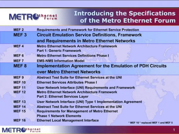
Approved MEF Specifications * MEF 6.1 replaced MEF 6., MEF 7.1 replaced MEF 7, MEF 10.2.1 & MEF 10 .2 replaced MEF 10.1.1, MEF 10.1, MEF 10 which replaced MEF 1 and MEF 5.
MEF Specifications Overview MEF 26 External Network to Network Interface (ENNI) – Phase I Purpose Specifies the reference point that is the interface between two Metro Ethernet Networks (MENs) where each operator MEN is under the control of a distinct administration authority. The ENNI is intended to support the extension of Ethernet services across multiple operator MENs. MEF 26.1 External Network Network Interface (UTA and VUNI) – Phase II Purpose This Technical Specification extends the ENNI by defining the UNI Tunnel Access (UTA) which associates a Virtual UNI (VUNI), a remote UNI, and at least one supporting OVC. Audience All, since it provides the fundamentals required to delivery services that extend Carrier Ethernet over multiple operator MENs and to build devices that support those services. It is especially relevant for Service Providers since it defines the standard mechanisms for interconnecting services across multiple operator’s MENs.
This Presentation • Purpose: • This presentation is an introduction to MEF 26 • Audience • Equipment Manufacturers building devices that will carry Carrier Ethernet Services. • Useful for Service Providers architecting their systems • Other Documents • Presentations of the other specifications and an overview of all specifications is available on the MEF web site • Other materials such as white papers and case studies are also available
MEF 26 Enhances Carrier Ethernet Attributes • Brings Carrier Ethernet to a new level by enabling interconnectivity between Carrier Ethernet networks from multiple operators
Carrier Ethernet growth challenges The success of Carrier Ethernet brings its own challenges, not the least of these is supporting interconnections between operators Until now, MEF specifications have not covered interconnection process relying on manual or ad hoc processes. MEF 26 Introduces a standard interconnection interface Making Carrier Ethernet interconnections simpler Increase the speed with which operators can cooperate to deliver services in Out of Franchise networks Accelerating the global adoption of Carrier Ethernet with a standard Global Interconnection mechanism MEF 26 Enables Carrier Ethernet Interconnects
Contents • Overview • Scope • Interconnection Interface • Operator Services Attributes • Examples • Summary
Background – UNI Functional Elements EMS Interface ETH Trunk Links Management plane Management plane Management plane Management plane ETH Access Link Control plane Control plane Data plane Cont rol plane Data plane Data plane Control plane Data plane UNI-C UNI-N Service Frame Flow UNI Reference Point • Relationship between service frames (user generated), control and Carrier Ethernet management frames • Subscriber to Subscriber service frames (including Subscriber’s data, control and management frames) are handled by UNI-C and UNI-N data plane functional elements • Control frames between Subscriber and Service Provider are handled by UNI-C and UNI-N control plane functional elements • Management frames between Subscriber and Service Provider are handled by UNI-C and UNI-N management plane functional elements
Carrier Ethernet Architecture Customer Site Service Provider 1 Service Provider 2 Customer Site UNI ENNI UNI I-NNI I-NNI CE CE ETH UNI-C ETH UNI-N ETH ENNI-N ETH ENNI-N ETH UNI-N ETH UNI-C NNI ENNI I-NNI Network to Network Interface External NNI Internal NNI UNI UNI-C UNI-N User Network Interface UNI-customer side UNI-network side The UNI is the physical demarcation point between the responsibility of the Service Provider and the responsibility of the Subscriber.
Contents • Overview • Scope • Definition and Architecture • Operator Services Attributes • Examples • Summary
The Scope of MEF 26 ENNI UNI 2 UNI 1 Operator B Operator A ENNI UNI 3 ENNI Operator C UNI 4 • Standard approach to implementing Ethernet Services as specified in MEF 10.2 and MEF 6.1 among UNIs supported by different Operator MENs • Specifies a standard Interconnection Interface between Operator MENs – the ENNI definition • Specifies Operator Services Attributes – the OVC definition UNI 2 UNI 1 Operator B UNI 3 Operator A ? Operator D Operator C UNI 4
What's new in MEF 26.1 • MEF 26.1 Consolidates the work in MEF 26, 26.0.1, 26.0.2, 26.0.3 • Introduces specifications for the support of Rooted-Multipoint EVCs as defined in MEF 10.2. • The definition and requirements for tunneling frames containing a Layer 2 Control Protocol on an Operator Virtual Connection. • Service Level Specification definitions and related requirements.
The ENNI Service Model ACME Mortar Subscriber contracts with Service Provider Service Provider contracts with each Operator UNI UNI EVC Operator Operator Operator
The Three Roles • Subscriber (as per MEF 10.2) • Ultimate Customer • Service Provider is a single point of contact • Service Provider (as per MEF 10.2) • Responsible for pulling together and managing the UNI to UNI Service • Is a customer of the Operator MEN(s) • Operator (New) • Responsible for behavior of Operator MEN only • May have limited knowledge of the UNI to UNI service • Many times the Service Provider is also an Operator but this is not required
Contents • Overview • Scope • Definition and Architecture • Operator Services Attributes • Examples • Summary
ENNI - Definition • ENNI is the reference point representing the boundary between two Operator MENs that are operated as separate administrative domains. • ENNI-N represents the functions necessary to support the protocols and procedures for the interface. ENNI-N1 ENNI-N2 Operator MEN 1 Operator MEN 2 ENNI ENNI Frames are exchanged between ENNI-N1 and ENNI-N2
Interconnection Interface Details • Physical Layer: Gigabit and 10Gigabit Ethernet IEEE Std 802.3 – 2005 • 1000Base-SX, 1000Base-LX, 1000Base T, 10GBASE-SR, • 10GBASE-LX4, 10GBASE-LR, 10GBASE-ER, 10GBASE-SW, 10GBASE-LW, 10GBASE-EW IEEE Std 802.3 – 2005 • One or more physical links • Link aggregation • Protection • Supported ENNI Frame Formats: • Untagged • Single S-Tag (TPID = 0x88A8) • Single S-Tag (TPID = 0x88A8) followed by a single C-Tag (TPID = 0x8100) • Maximum Transmission Unit • Size 1526 bytes required • Size 2000 bytes recommended
Protection at the ENNI • When there are two physical links, the Operator MEN must be able to support Link Aggregation with one link active and the other passive per IEEE Std 802.3 – 2005 • All subscriber traffic on active link with other link as backup • Operators may use other methods for protection if mutually agreed
Management at the ENNI • The Operator MEN must be able to support Link OAM as per IEEE Std 802.3 – 2005 • However it is recommended that the loopback capability be disabled
Contents • Overview • Scope • Definition and Architecture • Operator Services Attributes • Examples • Summary
Operator Service Attributes • Operator Service Attributes are behaviors that can be observed at and between External Interfaces. • ENNI and UNI are the External Interfaces. UNI Operator MEN ENNI UNI ENNI
Operator Virtual Connection (OVC) – 1 • Similar in concept to an EVC • An OVC constrains the exchange of frames between the External Interfaces of an Operator MEN • UNI to ENNI • ENNI to UNI • UNI to UNI • ENNI to ENNI • The OVC can support Hairpin Switching* at an ENNI • An ingress ENNI Frame can result in an egress ENNI Frame at the same ENNI • To describe this behavior the concept of an OVC End Point is introduced *Covered later in this presentation
Operator Virtual Connection (OVC) – 2 • An OVC is the association of OVC End Points. • Each OVC End Point is associated with a UNI or an ENNI and at least one must be associated with an ENNI • At each ENNI there is a way to map each S-Tagged ENNI Frame to at most one OVC End Point (and thus to at most one OVC) • At each UNI there is a way to map each Service Frame to at most one OVC End Point (and thus to at most one OVC) • An ingress frame mapped to an OVC End Point associated by an OVC can only result in an egress frame that is mapped to a different OVC End Point that is associated by the OVC
Two OVCs • An OVC can associate more than one OVC End Point that is at an ENNI • An OVC can associate at most one OVC End Point that is at a UNI UNI A OperatorMEN d e ENNI a Hairpin Switching b c f UNI B OVC End Point a OVC
Building EVCs with OVCs OperatorMEN A OperatorMEN B OperatorMEN C UNI P UNI R UNI T B3 B1 ENNI AB A1 A3 C1 A2 C4 B4 B2 ENNI BC OVC EndPoint x UNI Q UNI S UNI V OVC EndPoint y
Mapping Service Frames to OVC End Points At the UNI, the CE-VLAN ID of the Service Frame is used to map the frame to either an OVC End Point or an EVC UNI A e EVCAB ENNI OperatorMEN a b • The Subscriber at UNI A would perceive that CE-VLAN ID 59 maps to an EVC • UNI A is not necessarily devoted to a single Service Provider UNI B OVC End Point a OVC EVC
Mapping ENNI Frames to OVC End Points S-Tagged ENNI Frames are mapped to OVC End Points via the S-VLAN ID value End Point Map UNI A d e OperatorMEN a • When an ENNI Frame is hairpin switched, the S-VLAN ID value is changed • Multiple S-VLAN ID values can map to the same OVC End Point (called Bundling) b c ENNI f UNI B OVC End Point a OVC
“Stitching Together” OVCs to form EVCs Service Provider aligns the End Point Maps to build each EVC Service Provider View Subscriber View UNI Aa UNI Aa A4 OperatorMEN B UNI B UNI B A1 B1 Operator MEN A B3 A2 B2 A3 UNI Ab UNI Ab B End Point Map A End Point Map
Rooted-Multipoint (RMP) (added in 26.1) • An OVC that can associate at least one Leaf or Trunk OVC End Point is defined to have OVC Type of Rooted-Multipoint • The distinction between a Point-to-Point OVC or Multipoint-to-Multipoint OVC and a Rooted-Multipoint OVC with only Root OVC End Points is that a Leaf or Trunk OVC End Point can be added to such a Rooted-Multipoint OVC • To implement a Rooted-Multipoint EVC that spans multiple Operator MENs requires knowing whether the frame is the result of an ingress Service Frame at a Root UNI or a Leaf UNI. • Forwarding behavior of a Rooted-Multipoint (RMP) EVC is specified in MEF10.2 Subscriber View of the Rooted-Multipoint EVC
Key OVC Service Attributes – 1 • OVC Type: • Point-to-Point if the OVC associates two OVC End Points • Multipoint-to-Multipoint if OVC can associate more than two OVC End Points • Rooted Multipoint EVCs • OVC End Point List • The End Points associated by the OVC • OVC Maximum Transport Unit Size • Must be 1526 bytes, 2000 bytes recommended
Key OVC Service Attributes – 2 • CE-VLAN ID Preservation • An EVC built with OVCs with this attribute = Yes will preserve CE-VLAN IDs as required for EPL and EPLAN • CE-VLAN CoS Preservation • An EVC built with OVCs with this attribute = Yes will preserve CE-VLAN CoS as required for EPL and EPLAN • S-VLAN ID Preservation • Yes means that S-VLAN ID value is unchanged between ENNIs • Yes not allowed when hairpin switching • S-VLAN CoS Preservation • Yes means that S-VLAN PCP value is unchanged between ENNIs
Key OVC Service Attributes – 3 • Color Forwarding (Yes or No) • Yes means Yellow frames cannot be changed to Green • Unicast, Multicast, and Broadcast Frame Delivery • Deliver everywhere or deliver selectively, e.g., MAC address learning
Service Level Specification The OVC Related Performance Service Attributes specify the frame delivery performance between External Interfaces (EI). Eight performance metrics are detailed in this specification: • One-way Frame Delay, • One-way Frame Delay Range, • One-way Mean Frame Delay, • Inter-Frame Delay Variation, • One-way Frame Loss Ratio, • One-way Availability, • One-way High Loss Intervals, and • One-way Consecutive High Loss Intervals. For details refer to MEF Specification 23.1
Class of Service at the ENNI • Class of Service for an ENNI Frame is indicated by the S-Tag PCP value • Values specified in MEF 23 are mandated for classes H, M, and L • S-Tag PCP value indicates Class of Service for the receiving Operator MEN Example when A’s Gold is mapped to B’s Premium Gold Frame in Bhas PCP value set to4 (Premium) when sent to A Premium Frame in Ahas PCP value set to3 (Gold) when sent to B
Class of Service at the UNI • Consistent with Subscriber view as specified in MEF 10.2 • Based on OVC End Point (all Service Frames mapped to the OVC End Point have the same CoS)*, or • Based on C-Tag PCP, or • Based on DSCP *Subscriber perception is that EVC has a single CoS
Bandwidth Profiles at the ENNI • Based on same parameters and algorithm as in MEF 10.2 • Committed Information Rate (CIR) in bits/sec • Committed Burst Size (CBS) in bytes • Excess Information Rate (EIR) in bits/sec • Excess Burst Size (EBS) in bytes • Coupling Flag • Color Mode – always set to Color-Aware • Ingress Bandwidth Profile (policing) • Applied per OVC End Point or per OVC End Point and Class of Service • Green SLS applies, Yellow no SLS, Red discard • Egress Bandwidth Profile (shaping) • Applied per OVC End Point or per OVC End Point and Class of Service
Color Marking of ENNI Frames • Use either the DEI bit or the PCP of the S-Tag • Yellow indication as specified by MEF 23
Layer 2 Control Protocol Handling • Layer 2 Control Protocol Service Frame is described in MEF 10.2 • An ENNI Frame with a Destination MAC Address shown here is |defined to be a Layer 2 Control Protocol ENNI Frame • L2CP Service Frame or L2CP ENNI Frame is tunneled and delivered to all OVC End Points • Ingress L2CP ENNI Frame that does not have an S-Tag is not to be tunneled because the Operator has no information on which OVC to use to tunnel the frame
Topics not Covered by the Document • Service OAM • Expected to be covered in SOAM Fault Management and SOAM Performance Management documents • Additional protocols, e.g., Provider Backbone Bridges, MPLS • Later phase
Contents • Overview • Scope • Definition and Architecture • Operator Services Attributes • Examples • Summary
Notation and Conventions Operator MEN OVC End Point 1 ENNI UNI OVC
Ethernet Virtual Private Lines to a Hub Location Subscriber View UNI 2 EVC 1-2 UNI 1 EVC 1-3 UNI 3 EVC 1-4 UNI 4
Ethernet Virtual Private Lines to a Hub Location B UNI 2 A UNI 1 D C UNI 3 Service Provider View 5 4 3 1 2 11 6 12 7 13 9 8 10 15 14 16 UNI 4
Ethernet Private LAN Subscriber View UNI 2 EVC 1-2-3-4 UNI 1 UNI 3 UNI 4
Ethernet Private LAN B UNI 2 A UNI 1 UNI 3 Service Provider View Each OVC has CE-VLAN ID Preservation and CE-CoS Preservation in force (= Yes). 5 4 3 1 6 D C 7 8 9 10 16 UNI 4
Ethernet Private LAN with Hairpin Switching UNI 2 D C UNI 3 Service Provider View B Each OVC has CE-VLAN ID Preservation and CE-CoS Preservation in force (= Yes). 5 A 4 UNI 1 3 1 6 7 12 13 8 9 10 14 15 16 UNI 4
Rooted-Multipoint EVC – Trunk OVC End Points at the ENNI • Rooted-Multipoint EVC using Trunk OVC End Points at the ENNIs that connect three Operator MENs. • Each Operator MEN can receive ENNI Frames that originated at a Root UNI or a Leaf UNI. • Trunk OVC End Points and Trunk Identifiers at the ENNIs allows the Operator MEN to determine the type of ingress UNI and thus properly forward each ENNI Frame. Refer to the specification for additional examples
Summary MEF 26 – Phase I Introduces a standard interconnection interface Defines the External Network to Network Interface ENNI Defines Operator Services Attributes Defines a framework for extending an EVC between two UNIs separated by 3rd party operator networks MEF 26 – Phase II Introduces a standard interconnection interface introduces specifications for the support of Rooted-Multipoint EVCs Definition and requirements for tunneling frames containing a Layer 2 Control Protocol on an Operator Virtual Connection Service Level Specification definitions and related requirements