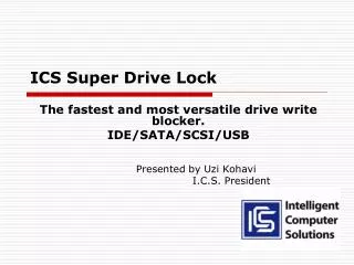
ICS Super Drive Lock
ICS Super Drive Lock. The fastest and most versatile drive write blocker. IDE/SATA/SCSI/USB Presented by Uzi Kohavi I.C.S. President. Milestones brought to you by the Company that invented the drive lock.

ICS Super Drive Lock
E N D
Presentation Transcript
ICS Super Drive Lock The fastest and most versatile drive write blocker. IDE/SATA/SCSI/USB Presented by Uzi Kohavi I.C.S. President
Milestonesbrought to you by the Company that invented the drive lock. • 2002 - ICS was the first to introduce the IDE drive lock to the Forensic Market. • ICS “pushed” the product concept through the US Justice system and it became the industry standard tool for Forensic investigators around the world. • ICS developed the USB/FireWire (1394B) and developed and built the FE and LE models for Guidance Software. • ICS has worked over 2 years on the development of the new generation of faster and more versatile SDL (Super Drive Lock).
Features • Stand-alone or housed in a 5.25” bay caddy, the SDL is connected to PC’s SATA or to an E-SATA controller card inside a PC. (Since some hard drives when attached to the SDL will not be recognized when connected to native SATA port on some PC’s, ICS recommends the use of E-SATA controller card to ensure 100% compatibility with both the PC and the drive connected to the SDL. Besides guaranteed drive detection the E-SATA controller supports “hot swap”).
Features • As stand alone (Used externally to the notebook) the SDL can be connected to a notebook, for example, via E-SATA Card Bus adaptor or with E-SATA notebook Express card.
Features • As a stand alone (used externally to the PC) the SDL can be connected to E-SATA port on a E-SATA PCI controller card plugged inside the PC.
Hard drive and Device Interfaces Front panel device ports: IDE: Supports all IDE drives. Provided with the unit: 1. UDMA 6” cable. SCSI: Supports all SCSI drives. Provided with the unit: • LVDS cable with terminators to support 320MByte/sec SCSI drives. • SCA50 and SCA80 adaptors to support 50 pin legacy drive and SCA80 drives. SATA/E-SATA: Supports SATA and E-SATA Drives and devices up to 3Gbit/sec. Provided with the unit: 1. SATA to SATA 15” power and data cable ( for SATA drive). 2. SATA to E-SATA 3’ cable ( for E-SATA devices and drives). USB: Supports variety of USB mass storage devices from flash drive to USB hard drives. (Actual Speed measured was 1.8GB/min. with theoretical limit of 3.6GB/min). Provided with the unit: 1. USB 2.0 6’ A to B cable.
E-SATA Support • SDL supplied with both E-SATA to E-SATA and E-SATA to SATA 3’ cables to provide the user with all possible connections.
3.3V Support • Supplied with 6” 6pin SATA power cable to support 3.3v SATA devices. • Note: The power connector in the front of the SDL has 6 pins for the 3.3v and 5v SATA power. For legacy 5v drives use the right 4 pins of the power connector.
Addition Cables Supplied extra cables: • 6” SATA data cable. • 36” Male/Female extension power cable. • 18” IDE UDMA cable.
Front Panel P-ATA Device Interface USB 2.0 Device Interface Drive Status LEDs Power LED S-ATA Device Interface Power Control Button Drive Power Output SCSI Device Interface
IDE 6” 6’ ESATA to ESATA IDE 18” 36” Extension Power M/F 6” Power SCSI LVDS 6” 3.3V Power 6’ USB Host SATA 6” 6’ USB device SATA DATA & Power 15” SCA-50 SCA-80 6’ SATA-ESATA
SDL Operation • A connected drive is detected by pressing and holding down the Power Control Button until the drive’s corresponding Status LED turns ON (Green), at which point the drive will power ON. The Power LED will also turn ON (Red). The PC’s O/S will detect the drive within a few seconds after the drive is powered ON. • Though multiple drives can be physically connected, only one drive can be selected for detection. • Power ON External USB drives using the drive’s own power supply, prior to pressing the Power Control Button.
Hardware Options • SDL can also use a USB/SATA bridge to connect the SDL to a PC or a notebook through USB port (speed will be reduced from SATA speed of 3GBit/Sec to 480Mbit/sec). When SDL is used externally (Desktop style), ICS recommends to use external power supply to power the SDL (Part of the USB Bridge). • The USB/SATA bridge. • E-SATA PCI or PCI-E controller card.
SDL Kit With Hard Case and Foam • F.GR-0029-000A $1250 • SDL • PCI-E • USB BRIDGE • PS • F.GR-0029-900A $1250 • SDL • PCI • USB BRIDGE • PS
Device Manager • The O/S “Device Manager” function can be used to verify that the drive was properly detected. The drive’s model information will be prefixed with an “IC” signature to indicate that the drive is connected using the SDL unit. • The drive’s model information may be truncated when using the SDL with E-SATA controller cards. • When using the SDL connected to the PC’s native S-ATA interface, it may be necessary to perform the following additional steps after powering ON the drive, before the O/S will properly detect the drive:- • Manually select the built-in O/S function which forces the O/S to detect new hardware. Ex. Select Windows XP “Scan for Hardware Changes” function located in “Device Manager”. • If the O/S does not detect the drive after selecting “Scan for Hardware Changes”, reset the PC with the drive connected and powered ON.
Device Manager screen shoot SDL Detected Drive
OS Messages with SDL Why does SDL not display messages? • SDL is designed to be “transparent” to the OS. • There is no need for a specific driver for the proper operation of the SDL. • Since the SDL is connected to the PC via the SATA protocol, there is no built in messages, beside the standard SATA that can be sent to the OS. • Messages that alert to the existence of drive lock or warning notification message when user is trying to modify a file on the “write blocked” hard drive” cannot be displayed. Note: Other devices that use SCSI or SCSI-like protocols, such as FireWire and USB, can use built-in error mechanism to alert the OS when the device is write protected.
SDL flashing LED • When a User connects and selects a drive or device to one of the SDL ports to be write-blocked there is a non-flashing green status LED that indicates that this device is in use. The other three drive status LED’s typically will not be in use. But these LED’s will start flashing green whenever there is an attempt to write to the drive or device that has been selected. These flashing LED’s will give assurance to the user that the SDL is functioning properly.
Firmware Updates • The Super Drive Lock’s firmware can be upgraded using the SDL’s USB interface connected to a PC. The USB cable is connected to the SDL’s dual USB/E-SATA connector located on the back of the unit. Detailed Firmware Upgrade instructions and files can be downloaded from the ICS Web Site. • Since the SDL's Firmware is the key to the unit's Forensic write-blocking functions it was important to develop a Firmware upgrade procedure which would be protected and not open to "hackers". Unlike other manufacturers of Write-Block devices, which can leave its Firmware open for "hacking" during automatic Firmware upgrade procedure, ICS designed the SDL Firmware upgrade procedure to isolate the SDL Firmware as much as possible from outside connections.
Firmware Updates continue • This design requires direct user interaction with the SDL unit when upgrading Firmware. The SDL Firmware upgrade procedure requires installing two SDL Upgrade Utilities to program the SDL’s two firmware chips, designated as “software” and “firmware”. The upgrade is performed by connecting the SDL to a standalone PC, which is isolated from a network or internet connection and pressing the SDL's front panel power button in a specific sequence.
Firmware update through USB port in the back of the SDL (dual port)
Trouble shooting tips • It may be necessary to perform the following additional steps after powering ON the drive before the O/S will properly detect the drive. This is especially true if the SDL is connected using the PC’s native S-ATA interface. • Manually select the built-in O/S function which forces the O/S to detect new hardware. Ex. Select Windows XP “Scan for Hardware Changes” function located in “Device Manager”. • If the O/S does not detect the drive after selecting “Scan for Hardware Changes”, reset the PC with the drive connected and powered ON.
Price comparison • SDL(F.GR-0028-000A)MSRP is $950 (all-in- one; includes all the necessary cables adapters) • Tableau prices** T35ES with E-SATA $332 T5 with SCSI $359 T4 with USB $269 T35i Front panel Bay for IDE and SATA $404 T335 2 SATA and IDE $585 Price of a multiple device to achieve the similar functionality externally is $332+$359+$269=$960 Add all the necessary cables the price is around $1100 (**Prices sourced from ForensicPC.com)
The End • Thank you