Generator Equations Galore
110 likes | 132 Vues
Explore equations for smooth-rotor, 2-pole generator characteristics, magnetism, harmonics suppression, winding distribution, and transformer representation. Learn about power factor, grid connection, and equilibrium. Discover insights into exciting rotor with DC and connections for optimal performance.

Generator Equations Galore
E N D
Presentation Transcript
Generator Equations Galore Summary of the equations for the magnetic and electrical characteristics of a smooth-rotor, 2-pole generator as developed in class to find: Rotor and stator inductances and their mutual inductance The generator equivalent circuit Suppression of harmonics at frequencies: 3n times the fundamental
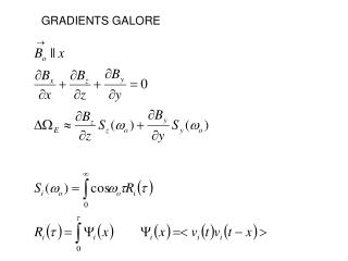
Rotor and Stator Coupling with Distributed Windings on Both Rotor and Stator • Sinusoidal flux distribution over rotor surface with peak B given by the usual use of Ampere’s Law • Not all flux goes through all turns of the rotor so inductance is slightly smaller than N times the core flux • With cosine distributed stator windings, the mutual inductance has the same form
What’s Going on with Matrix Representation of a Transformer • Every coil current induces a flux in every other coil proportional to that current • The voltage across a coil is the time derivative of the flux through the coil – Faraday’s Law • Multiplying out the stator voltage gives an equation equivalent to a voltage source in series with an inductor. That inductor has the full inductance of the stator winding so the air gap must be chosen to optimize this inductance.
Exciting the Rotor with DC – No Voltage Variation across Its Terminals! • Multiply the matrix row onto the current vector for the rotor voltage – in a single-phase generator, this had a time dependent value. • First term vanishes because the rotor current is DC. Of course, the rotor DC voltage must be enough to satisfy Ohm’s law: • Each squared cosine term has a DC term and a cosine at twice the frequency. The derivative of the DC term is zero and the set of cosines is a phasor sum that is also zero.
Why? What’s Going On? • Exciter produces sinusoidal radial B field in the air gap oriented with the peak along one axis – shown here as a vector • Output current produces similar field rotating in the same direction and speed but directed opposing the exciter field at a different angle • Net is smaller field oriented between them at the angle of the generator output voltage
Why a Wye to Delta Connection at Generator Output? • The phase shift in a three-phase system is actually a time delay rather than a phase shift from circuit reactances because the shift is from a delay as the rotor turns by an amount per phase step of: • Suppose the m’th winding has a harmonic in its voltage at frequency 3n times the fundamental • This means that all three output nodes have the same voltage relative to the center of the star and a delta-wound transformer will have no harmonic at that frequency in its magnetic field!!
Connecting to the Grid: The Power Factor of the Transmission System and Required Rotor Phase Lag • The grid appears to a generator as a “stiff” AC source that is much stronger than any single generator, being the aggregate of hundreds of sources totaling power that is at least 8 to 200 times greater than a typical generator. • The transformers and transmission lines that connect this generator to the grid add a series inductance that makes this appear as a load with power factor < 1. Typically generators are specified to run into a power factor of 0.90 or an angle of degrees. • This equivalent circuit is for one, wye-connected phase of the three phase system.
Phasor Model of the Generator to Grid Connection at Startup and Equilibrium • Equilibrium operation has the generator output current and voltage at nameplate rating. The voltage is higher than the grid because of the grid inductance and power factor. • The exciter current sets the length of E, the magnitude of the emf. • The turbine torque sets the angle to balance the turbine power to the real power delivered to the grid. • At startup there is no grid connection and no current. The generator voltage is E and that must be brought to match frequency, phase and magnitude before the switch is closed. • After the connection is made, the torque and excitation increase together until equilibrium is reached