The Conceptual Solution for LHC Collimation Phase II
640 likes | 665 Vues
The Conceptual Solution for LHC Collimation Phase II. R. Assmann, CERN/BE 2/4/2009 for the Collimation Project Conceptual Review Phase II, CERN. Conceptual Review Phase II Collimation. Despite tight resources we found the time to work out a conceptual

The Conceptual Solution for LHC Collimation Phase II
E N D
Presentation Transcript
The Conceptual Solution for LHC Collimation Phase II R. Assmann, CERN/BE 2/4/2009 for the Collimation Project Conceptual Review Phase II, CERN
Conceptual Review Phase II Collimation Despite tight resources we found the time to work out a conceptual solution for reaching nominal and ultimate intensities in the LHC. Many thanks to all who helped. • Now: Have solution reviewed and start technical design work, if our proposals are supported. • What this review is: Collect and present solutions for all known problems (p, ions, experiments). Present a conceptual solution and readiness for starting technical design work. • What this review is not: Detailed decision on technical choices e.g. for jaw material of phase II secondary jaws. No presentation of detailed technical designs, costs, assessment of resulting work for the super-conducting ring. • Following along our project plan, as discussed in AB and the LHC project and as sent to the DG in 2007. • R. Assmann, CERN
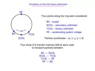
1) Reminder: The LHC Challenge The Large Hadron Collider: Circular particle physics collider with 27 km circumference. Two colliding 7 TeV beams with each 3 × 10¹⁴protons. Super-conducting magnets for bending and focusing. Start of beam commissioning: May 2008. LHC nominal parameters Number of bunches: Bunch population: Bunch spacing: Particle physics reach defined from: 2808 1.15e11 25 ns Top energy: 14 TeV 1) Center of mass energy Proton energy: Transv. beam size: Bunch length: Stored beam energy: 7 TeV ~ 0.2 mm 8.4 cm 360 MJ super-conducting dipoles Injection: 1034cm-2s-1 Proton energy: Transv. Beam size: Bunch length: 450 GeV ~ 1 mm 18.6 cm 2) Luminosity R. Assmann, CERN 3
LHC Luminosity Luminosity can be expressed as a function of transverse energy density rein the beams at the collimators: • d = demagnification (bcoll/b*) Np= protons per bunch frev= revolution freq. Eb= beam energy Various parameters fixed by design, for example: • – Tunnel fixes revolution frequency. – Beam-beam limit fixes maximum bunch intensity. – Machine layout and magnets fix possible demagnification. – Physics goal fixes beam energy. Luminosity is increased via transverse energy density! • R. Assmann, CERN 4
pp, ep, and ppbar collider history Higgs + SUSY + ??? ~ 80 kg TNT 2008 Collimation Machine Pro- tection 1992 SC magnets 1971 1987 1981 The “new Livingston plot“ of proton colliders: Advancing in unknown territory! A lot of beam comes with a lot of garbage (up to 1 MW halo loss, tails, backgrd, ...) Collimation. Machine Protection. R. Assmann, CERN
The Luminosity Challenge d = demagnification (bcoll/b*) Np= protons per bunch frev= revolution freq. Eb= beam energy The LHC is targeted to handle 1000 times higher energy density (see previous plot). • Why then is the luminosity not 1000 times higher than Tevatron? • Tevatron revolution frequency is 4 times higher, while beam energy is 7 times smaller than in LHC! • We need about 20 times more stored energy in LHC than in Tevatron for the same luminosity! • At the same time, quench limits are lower in the LHC than in Tevatron. • Stringent requirements for lifetimes and collimation efficiency in LHC. • R. Assmann, CERN
2) Design Parameters Most important design parameters: • – Cleaning efficiency – Peak loss rate of stored beam – LHC quench limit (taken from design) – BLM threshold with respect to quench limit (taken from design) Performance and requirements depend on design parameters and assumptions. • Without beam experience we cannot be sure about our assumptions. • Base as much as possible on the experience from present and past colliders! • R. Assmann, CERN
Required Cleaning Efficiency Quench threshold (7.6 ×10⁶p/m/s @ 7 TeV) Allowed intensity Illustration of LHC dipole in tunnel max RqFBLMLdil/c Np Cleaning inefficiency = Number of escaping p (>10s) Number of impacting p (6s) Loss length BLM threshold (e.g. 30%) Beam lifetime (e.g. 0.2 h minimum) Collimation performance can limit the intensity and therefore LHC luminosity. R. Assmann, CERN 8
Specifying Peak Loss of Stored Beam LHC specification is demanding! Require outstanding LHC stability! Peak fractional loss of 0.1 % per second. LHC design value: Tevatron 2009: 10-3/s > 6 10-3/s R. Assmann, CERN
Major Function: Preventing Quenches Shock beam impact: 2 MJ/mm2in 200 ns (0.5 kg TNT) • Maximum beam loss at 7 TeV: 1% of beam equally lost over 10 s • 500 kW Quench limit of SC LHC magnet: • 8.5 W/m R. Assmann, CERN
Tevatron 2009: End of Ramp Losses Analysis of 19 physics fills (two weeks in March 2009) LHC assumption Integrated losses during ramp: 2 - 4 % R. Assmann, CERN
The Phased LHC Collimation Solution Phase I (initial installation): • – Relying on very robust collimators with advanced but conservative design. – Perceived to be used initially (commissioning) and always in more unstable parts of LHC operation (injection, energy ramp and squeeze). – Provides excellent robustness and survival capabilities. – OK for ultimate intensities in experimental insertions (triplet protection, physics debris). – Has limitations in cleaning efficiency (betatron & momentum) and impedance. – Demanding R&D, production and installation schedule. Phase II (upgrade for nominal/ultimate intensities): • – Upgrade for higher LHC intensities, complementing phase I. – To be used in more stable parts of operation like physics (robustness can be compromised). – Fixes limitations in efficiency, impedance and other issues. R. Assmann, CERN
3) The Phase I System Includes 112 collimators in the LHC ring and the transfer lines from the SPS to the LHC. In addition 19 spare collimators. • 38 tunnel locations equipped with cables, water connections, vacuum pumping, instrumentation and replacement chambers (preparation phase II). • We use 10 types of collimators in phase I, robust collimators close to beam (survives injection and dump failures) and non-robust collimators further retracted: • – Robust primary cleaning collimators TCP (fiber-reinforced carbon jaws). – Robust secondary cleaning collimators TCSG (fiber-reinforced carbon jaws). – Non robust cleaning absorbers TCLA (copper-tungsten jaws). – Non robust tertiary collimators TCT (copper-tungsten jaws): cleaning, triplet protection. – Non robust experimental absorbers TCLP (copper jaws): catching physics debris. – Several special type collimators, robust and not robust. Essentially fully installed by now (except where conflict with Roman Pots). • R. Assmann, CERN
The Phase 1 Collimator 1.2 m 3 mm beam passage with RF contacts for guiding image currents Designed for maximum robustness: Advanced CC jaws with water cooling! Other types: Mostly with different jaw materials. Some very different with 2 beams! 360 MJ proton beam R. Assmann, CERN
System Design Momentum Collimation Betatron Collimation “Phase 1” Layout C. Bracco R. Assmann, CERN
Multi-Stage Cleaning & Protection Without beam cleaning (collimators): Beam propagation Quasi immediate quench of super- conducting magnets (for higher intensities) and stop of physics. Core Required cleaning efficiency: always better than 99.9%. Unavoidable losses Primary halo (p) Secondary halo p Shower p Tertiary halo p Impact parameter ≤ 1 mm p collimator Primary e Secondary p collimator Absorber Shower Absorber e SC magnets and particle physics exp. Super- conducting magnets W/Cu W/Cu CFC CFC R. Assmann, CERN
Phase I in Tunnel RADIATION-HARD CABLE PATH WATER FEEDS COLLIMATOR COLLIMATOR CABLE TRAYS PHASE I/II WATER DISTRIBUTION BEAM PIPES TRANSPORT ZONE
Collimator Operation 1stBeam Day; Use as Target/Stopper Collimator in IP5 closed Interesting now… Background later… R. Assmann, CERN
Performance Limits with Phase I Beam1, 7 TeV Betatron cleaning Ideal performance TCDQ Efficiency 99.998 % per m Local inefficiency [1/m] Quench limit (nominal I, t=0.2h) Beam2, 7 TeV Betatron cleaning Ideal performance TCDQ Efficiency 99.998 % per m Quench limit (nominal I, t=0.2h) 99.998 % needed 99.995 % predicted Local inefficiency: #p lost in 1 m over total #p lost = leakage rate R. Assmann, CERN 19
Impact of Imperfections on Inefficiency (Leakage Rate) – 7 TeV worse better PhD C. Bracco 40% intensity ideal reach R. Assmann, CERN 20
Proton Losses in Dispersion Suppressor Downstream IR7 halo Collisions p on carbon generate off-momentum protons (mostly single-diffractive scattering). Are kicked out by the first bending dipoles (classical spectrometer). R. Assmann, CERN
Summary Limits of LHC Collimation Phase I Cleaning efficiency (require > 99.995%/m): • – Ideal performance reach: 40% of nominal LHC intensity (factor 100 better cleaning than Tevatron/HERA) – With imperfections: loose up to factor 11 in performance (factor 10 better cleaning than Tevatron/HERA) – Imperfections must be minimized and special setup routines are being developed. phase II. – Upgrade of collimation required Impedance: • – Beam stability limit:40% of nominal beam intensity Other possible limitations: • – Collimator lifetime with radiation damage R. Assmann, CERN
Phase I Intensity Limit vs Loss Rate 5 TeV nominal worse better R. Assmann, CERN 23
Phase I Intensity Limit vs Loss Rate 7 TeV nominal worse better R. Assmann, CERN 24
Limit Stored Energy vs Beam Energy R. Assmann and W. Herr R. Assmann, CERN 25
Limit Peak Instantaneous Luminosity R. Assmann and W. Herr beam loss limited R. Assmann, CERN 26
Why Do We Believe Strongly in Limitation? Because it is related to clear and well-known physics processes: • – Primary collimators intercept protons and ions, as they should. – Small fraction of protons receive energy loss but small transverse kick (single- diffractive scattering), ions dissociate, … – Subsequent collimators in the straight insertion (no strong dipoles) cannot intercept these off-momentum particles (would require strong dipoles). – Affected particles are swept out by first dipoles after the LSS. Main bends act as spectrometer and off-momentum halo dump quench. Off-momentum particles generated by collimators MUST get lost at the dispersion suppressor (if we believe in physics and LHC optics). • No hope that this is not real (e.g. LEP2 was protected against this – not included for the LHC design and too late to be added when I got involved). • Predicted for p, ions of different species (with different programs). • R. Assmann, CERN 27
Other Limit: Radiation Damage (p & ion) A. Ryazanov Working on understanding radiation damage to LHC collimators from 1016impacting protons of 7 TeV per year. Also with BNL/LARP… … in addition shock wave models… R. Assmann, CERN
Radiation Effect on Electrical Resistivity Change in electrical resistivity [%] Four times electrical resisitivity: higher impedance! A. Ryazanov Radiation dose [dpa] Collimator properties will change with time many properties checked. Beneficial to distribute radiation over phase I and phase II collimators! R. Assmann, CERN
4) The Phase II Solution Phase 2 collimation project on R&D has been included into the white paper: • – We set up project structure in January 2008. Key persons in place. Work packages agreed. – Two lines: (1) Upgrade of collimation and improved hardware. (2) Preparation of beam test stand for test of advanced collimators. – Review in February 2009 to take first decisions. US effort (LARP, SLAC) is ongoing. First basic prototype results shown at EPAC08. • FP7 request EUCARD with collimation work package: • – Makes available significant additional resources (enhancing white paper money). – Remember: Advanced collimation resources through FP7 (cryogenic collimators with GSI, crystal collimation, e-beam scraper, …). R. Assmann, CERN
Phase II: Part 1 Modification of SC dispersion suppressors to accommodate additional collimators (“cryo-collimators”) R. Assmann, CERN
The 2008 Breakthrough The limitation (single-diffractive p scattering, ion fragmentation/dissociation) was understood early on in 2003/4 but it was too late to change cold areas. • Possible solutions were discussed: • – New, shorter and stronger dipole magnets to place collimators into SC area. – Enlarged tunnel in cleaning insertions to place stronger dogleg dipole magnets and put dispersive chicanes. – Other drastic measures… – All was very heavy and not really realistic. Breakthrough in 2008: We realized that we can use missing dipole space and rearrange magnets to create proper space for additional collimators. • Efficiency gain: Factor 90 for imperfect machine predicted Factor 15 for perfect machine simulated • R. Assmann, CERN
Schematic Solution Efficiency Collimator Warm cleaning insertion (straight line) SC bend dipole (acts as spectrometer) SC quad Off-momentum particles generated by particle- matter interaction in collimators (SD scattering) Ideal orbit (on momentum) Add cryogenic collimator, using space left by missing dipole (moving magnets) + metallic phase 2 collimators in IR3 and IR7 R. Assmann, CERN
halo Downstream of IR7 b-cleaning Halo Loss Map Losses of off-momentum protons from single-diffractive scattering in TCP cryo-collimators Upgrade Scenario NEW concept See talk J. Jowett transversely shifted by 3 cm without new magnets and civil engineering halo -3 m shifted in s +3 m shifted in s
99.997 %/m 99.99992 %/m Proton losses phase II: Zoom into DS downstream of IR7 quench level Very low load on SC magnets less radiation damage, much longer lifetime. T. Weiler Impact pattern on cryogenic collimator 2 Impact pattern on cryogenic collimator 1 Cryo-collimators can be one-sided! See talk T. Weiler R. Assmann, CERN
FLUKA Results Proton and ion tracking does not take into account showers. • FLUKA provides more realistic estimates of energy deposition in SC magnets. • Results for p: • Case Phase I Phase II, 1 m Cu Phase II, 1 m W Peak Energy Deposition 5 mW/cm3 1 mW/cm3 0.3 mW/cm3 Factor 15 predicted from FLUKA simulations for p. Similar gains for ions. • See talk F. Cerutti. • Additional gain expected with imperfections. See talk S. Redaelli. • Total efficiency gain will be between factor 15 to 90! • R. Assmann, CERN
Ion Efficiency with Cryo-Collimators Phase I: Many losses. Limited to ~50% of nominal ion intensity. See talk G. Bellodi. Phase II: No losses Solved. R. Assmann, CERN
Remarks Cryo-Collimators Strictly speaking we mean collimators in the cryogenic region just after the long straight sections. • These cryo-collimators can be warm elements (requiring cold-warm transitions) or cryogenic elements. • Term comes from GSI, as designed for the FAIR project. They use collimators at about 50 K. • Technical choice must be outcome of detailed technical design work. • FLUKA studies ongoing to define best length and material. • For our studies: Cryo-collimator = 1 m long Cu or W block • Radiation studies show that both materials are feasible. Installation constraints from radiation must be taken into account. See talk H. Vincke. • R. Assmann, CERN
Load Experimental Collimators (Beam 1) See talks T. Weiler and G. Bellodi. Figure shows average reduction in loss at horizontal tertiary collimators in the various insertions (collimation halo load). CMS is not improved as cryo-collimators were not included in IR3. • Phase II collimation upgrade reduces losses in IR’s by a factor up to 100! • R. Assmann, CERN
Phase II: Part 2 Advanced Secondary Collimators for Pre-Equipped Phase II Slots R. Assmann, CERN
LHC Phase II Cleaning & Protection Beam axis Beam propagation Impact parameter Collimator Core Particle Unavoidable losses 1. Phase 2 materials for system improvement. Primary halo (p) 2. Crystals AP under study (surface effects, dilution, absorption of extracted halo). Secondary halo p Shower p Tertiary halo p Impact parameter ≤ 1 mm p collimator collimator Primary Primary e Phase 1 Colli- p Hybrid Colli- mator TCSM mator TCSG Absorber Shower Absorber e SC magnets and particle physics exp. Super- conducting magnets Phase 1 Colli- mator TCSG W/Cu W/Cu CFC Phase 2 material CFC 41 Low electrical resistivity, good absorption, flatness, cooling, radiation, …
Phase II Secondary Collimator Slots PHASE I TCSG SLOT EMPTY PHASE II TCSM SLOT (30 IN TOTAL)
Phase II Advanced Secondary Collimators Will not very much improve the cleaning efficiency. • However, will implement other improvements: • – Reduction in impedance (see talk E. Metral). – Non-invasive and fast collimator setup with BPM buttons in jaw (see talk A. Bertarelli and S. Redaelli). – Improvement of lifetime for warm magnets in cleaning insertion by factor ~3 (see talk F. Cerutti). – Improvement of lifetime for phase I collimators as radiation load is spread over phase I and phase II collimators. Design and prototyping has started. Material will be decided based on LHC beam experience: either Cu or ceramics/advanced composites. See talks E. Metral, A. Bertarelli, T. Markiewicz. • Will not ensure collimator robustness but may include rotatable solution for handling many damages in-situ. See talk T. Markiewicz. • R. Assmann, CERN
Impedance with SLAC Design and Cryo- Collimators Baseline: Stabilize with transverse feedback! See talk E. Metral. Metallic Cu secondary collimators (phase II) require less gap opening for stability! R. Assmann, CERN
Phase II: Tradeoff p Inefficiency – Impedance (if Transverse Feedback Cannot Stabilize) With copper secondary collimators and cryo-collimators! Inefficiency Stable working point Phase II allows stable working point by opening gaps! Requires larger b*. Impedance R. Assmann, CERN
Non-Invasive Set-up with BPM Buttons R. Assmann, CERN
Non-Invasive Set-up with BPM Buttons 1) Center jaw ends around beam by zeroing difference signal from pair of pickups. R. Assmann, CERN
Non-Invasive Set-up with BPM Buttons 2) Put the same gap at both ends as measured from jaw position (phase 1 feature). R. Assmann, CERN
BPM integration Integration of BPMs into the jaw assembly gives a clear advantage for set-up time Prototyping started at CERN BPM pick-ups BPM cables and electrical connections R. Assmann, CERN A. Bertarelli – A. Dallocchio LHC Collimation Phase II – Design Meeting – 19/09/2008
Test Needs: HiRadMat Phase I was putting robustness first. • Phase II considers using less robust collimators in stable physics. • Assumptions: • – Rare damaging events. – Benign damage in case of hit. Risk of non-benign risk must be assessed before installation of such collimators. • Requires beam test area HiRadMat. 2 MJ pulsed beam at ~450 GeV from SPS for accident scenario test. • See talk E. Eftiomoupolos. • R. Assmann, CERN