Mastering Processor Control Units
Learn how to build a complete example processor with a control unit that converts binary instructions to datapath signals. Understand instruction formats, block diagrams, program counters, jumps, and more. Enhance your knowledge on control signals and data paths.

Mastering Processor Control Units
E N D
Presentation Transcript
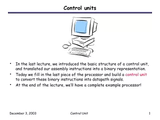
Control units • In the last lecture, we introduced the basic structure of a control unit, and translated our assembly instructions into a binary representation. • Today we fill in the last piece of the processor and build a control unit to convert these binary instructions into datapath signals. • At the end of the lecture, we’ll have a complete example processor! Control Unit
D Register file A B WR DA AA BA constant 1 0 Mux B MB FS A B ALU G ADRS DATA Data RAM OUT V C N Z MW 0 1 Mux D MD Datapath review • Set WR = 1 to write one of the registers. • DA is the register to save to. • AA and BA select the source registers. • MB chooses a register or a constant operand. • FS selects an ALU operation. • MW = 1 to write to memory. • MD selects between the ALU result and the RAM output. • V, C, N and Z are status bits. Control Unit
15 9 8 6 5 3 2 0 Instruction format review • We have three different instruction formats, each 16 bits long with a seven-bit opcode and nine bits for source registers or constants. • The first three bits of the opcode determine the instruction category, while the other four bits indicate the exact instruction. • For ALU/shift instructions, the four bits choose an ALU operation. • For branches, the bits select one of eight branch conditions. • We only support one one load, one store and one jump instruction. Control Unit
Block diagram of a processor • The control unit connects programs with the datapath. • It converts program instructions into control words for the datapath, including signals WR, DA, AA, BA, MB, FS, MW, MD. • It executes program instructions in the correct sequence. • It generates the “constant” input for the datapath. • The datapath also sends information back to the control unit. For instance, the ALU status bits V, C, N, Z can be inspected by branch instructions to alter a program’s control flow. Program Control signals Control Unit Datapath Status signals Control Unit
ADRS Instruction RAM OUT ADRS DATA Data RAM OUT MW Where does the program go? • We’ll use a Harvard architecture, which includes two memory units. • An instruction memory holds the program. • A separate data memory is used for computations. • The advantage is that we can read an instruction and load or store data in the same clock cycle. • For simplicity, our diagrams do not show any WR or DATA inputs to the instruction memory. • Caches in modern CPUs often feature a Harvard architecture like this. • However, there is usually a single main memory that holds both program instructions and data, in a Von Neumann architecture. Control Unit
Program counter • A program counter or PC addresses the instruction memory, to keep track of the instruction currently being executed. • On each clock cycle, the counter does one of two things. • If Load = 0, the PC increments, so the next instruction in memory will be executed. • If Load = 1, the PC is updated with Data, which represents some address specified in a jump or branch instruction. Data Load PC ADRS Instruction RAM OUT Control Unit
Data Load PC Instruction Decoder ADRS Instruction RAM OUT DA AA BA MB FS MD WR MW Instruction decoder • The instruction decoder is a combinational circuit that takes a machine language instruction and produces the matching control signals for the datapath. • These signals tell the datapath which registers or memory locations to access, and what ALU operations to perform. (to the datapath) Control Unit
PC Branch Control V C N Z ADRS Instruction RAM OUT Instruction Decoder DA AA BA MB FS MD WR MW Jumps and branches • Finally, the branch control unit decides what the PC’s next value should be. • For jumps, the PC should be loaded with the target address specified in the instruction. • For branch instructions, the PC should be loaded with the target address only if the corresponding status bit is true. • For all other instructions, the PC should just increment. Control Unit
Branch Control V C N Z PC ADRS Instruction RAM OUT Instruction Decoder DA AA BA MB FS MD WR MW That’s it! • This is the basic control unit. On each clock cycle: 1. An instruction is read from the instruction memory. 2. The instruction decoder generates the matching datapath control word. 3. Datapath registers are read and sent to the ALU or the data memory. 4. ALU or RAM outputs are written back to the register file. 5. The PC is incremented, or reloaded for branches and jumps. Control Unit
D Register file A B WR DA AA BA Branch Control V C N Z constant PC 1 0 Mux B MB ADRS Instruction RAM OUT ADRS DATA Data RAM OUT FS A B ALU G MW V C N Z Instruction Decoder DA AA BA MB FS MD WR MW 0 1 Mux D MD The whole processor Control Unit Datapath Control Unit
ADRS Instruction RAM OUT Instruction Decoder DA AA BA MB FS MD WR MW Implementing the instruction decoder • The first thing we’ll look at is how to build the instruction decoder. • The instruction decoder’s input is a 16-bit binary instruction I that comes from the instruction memory. • The decoder’s output is a control word for the datapath. This includes: • WR, DA, AA, BA, and MD signals to control the register file. • FS for the ALU operation. • MW for the data memory write enable. • MB for selecting the second operand. • We’ll see how these signals are generated for each of the three instruction formats. Control Unit
D Register file A B WR DA AA BA constant 1 0 Mux B MB ADRS DATA Data RAM OUT FS A B ALU G MW V C N Z 0 1 Mux D MD MB, MD, WR and MW • The following table shows the correct signals MB, MD, WR and MW for each of the eight different instruction categories we defined. • As mentioned last time, this is the sense in which these categories contain “similar” instructions. Control Unit
MB, MD, WR and MW • The following table shows the correct signals MB, MD, WR and MW for each of the eight different instruction categories we defined. • As mentioned last time, this is the sense in which these categories contain “similar” instructions. Control Unit
Eight categories of instructions • There are several patterns visible in this table. • MW = 1 only for memory write operations. • MB = 1 only for immediate instructions, which require a constant. • MD is unused when WR = 0. • Jumps and branches modify neither registers nor main memory. Control Unit
Generating MB, MD, WR, and MW • Because of the way we defined our opcodes, the four control signals MB, MD, WR and MW can be expressed as functions of the first three opcode bits, or instruction bits I15, I14 and I13. MB = I15 MD = I14 WR = I14’ + I15’ I13 MW = I15’ I14 I13’ Control Unit
5 FS FS4 FS3 FS2 FS1 FS0 = I13 I12 I11 I10 I9 Generating FS • Yesterday, we used an ALU function selector as the last four bits in the opcode of ALU and shift instructions. • For example, a register-based XOR has the opcode 0001100. • The first three bits 000 indicate a register-based ALU instruction. • 1100 is the ALU code for the XOR function. • Thus, the control unit can “generate” the ALU’s FS control signal just by taking it directly out of the instruction opcode. • For register and immediate-format instructions: Control Unit
D Register file A B WR DA AA BA constant 1 0 Mux B MB FS A B ALU G ADRS DATA Data RAM OUT V C N Z MW 0 1 Mux D MD FS for branch instructions • FS would be don’t-cares for loads, stores and jumps, which do not involve the ALU. • However, FS is required for branch instructions, which depend on the ALU’s status bit outputs. • For example, in BZ R3, -24 the contents of R3 must go through the ALU so that Z will be set appropriately. • For our branches, we just need the ALU function “G = A” (FS = 00000 or 00111). Control Unit
D Register file A B WR DA AA 3 3 3 BA DA AA BA Generating DA, AA, BA • The register file addresses DA, AA and BA can be taken directly out of the 16-bit binary instructions. • Instruction bits 8-6 are the destination register, DA. • Bits 5-3 are fed directly to AA, the first register file source. • Bits 2-0 are connected directly to BA, the second source. • This clearly works for a register-format instruction where bits 8-6, 5-3 and 2-0 were defined to hold the destination and source registers. Control Unit
3 3 3 DA AA BA Don’t-care conditions • In immediate-format instructions, bits 2-0 store a constant operand, not a second source register! • However, immediate instructions only use one source register, so the control signal BA would be a don’t care condition anyway. • Similarly, jump and branch instructions require neither a destination register nor a second source register. • So we can always take DA, AA and BA directly from the instruction. DA2 DA1 DA0 = I8 I7 I6 AA2 AA1 AA0 = I5 I4 I3 BA2 BA1 BA0 = I2 I1 I0 Control Unit
Branch Control V C N Z PC ADRS Instruction RAM OUT Instruction Decoder DA AA BA MB FS MD WR MW More about the branch control unit • Next, let’s see how to manage the control flow of a program. • The branch control unit needs a lot of information about the current instruction. • Whether it’s a jump, a branch, or some other instruction. • For branches and jumps, the target address. • For branches, the specific branch condition. • All of this can be generated by the instruction decoder, which has to process the instruction words anyway. Control Unit
Branch Control V C N Z PC ADRS Instruction RAM OUT PL JB BCAD Instruction Decoder DA AA BA MB FS MD WR MW Branch control unit inputs and outputs • Branch control inputs: • PL, JB, BC and AD are output by the instruction decoder, and carry information about the current instruction. • Status bits V, C, N and Z come from the datapath. • The current PC is needed for PC-relative mode jumps and branches. • Branch control outputs: • A Load signal for the PC. • When Load = 1, the branch control unit also generates the target address to jump or branch to. Control Unit
Branch Control V C N Z PC ADRS Instruction RAM OUT PL JB BCAD Instruction Decoder DA AA BA MB FS MD WR MW Branch control unit inputs • The decoder sends the following data to the branch control unit: • PL and JB indicate the type of instruction. • BC encodes the kind of branch. • AD determines the jump or branch target address. Control Unit
Generating PL and JB • The instruction decoder generates PL and JB from instruction opcodes. • Note that if PL = 0, then the value of JB doesn’t matter. • As expected, PL and JB only matter for jumps and branches. • From this table you could derive: PL = I15 I14 JB = I13 Control Unit
3 3 3 BC AD AD Generating BC and AD • We defined the branch opcodes so that they already contain the branch type, so BC can come straight from the instruction. • AD can also be taken directly out of the instruction. BC2 BC1 BC0 = I11 I10 I9 AD5 AD4 AD3 AD2 AD1 AD0 = I8 I7 I6 I2 I1 I0 Control Unit
Branch Control V C N Z PC PL JB BCAD Branch control unit • Now we’ve seen how the instruction decoder generates PL, JB, BC and AD. How does the branch unit use these to control the PC? • There are three cases, depending on the values of PL and JB. • If PL = 0, the current instruction is not a jump or branch, so the branch control just needs to make the program counter increment, and execute the next instruction. Control Unit
Branch Control V C N Z PC PL JB BCAD Jumps • If PL = 1 and JB = 1, the current instruction must be a jump. • We assume PC-relative addressing, so the jump “offset” (AD) must be added to the current PC value, and then stored back into the PC. • The branch control unit would contain an adder just for computing the target address. • Again, AD is signed so we can jump forwards or backwards. Control Unit
Branch Control V C N Z PC PL JB BCAD Branches • If PL = 1 and JB = 0, the current instruction is a conditional branch. • The branch control unit first determines if the branch should be taken. • It checks the type of branch (BC) and the status bits (VCNZ). • For example, if BC = 011 (branch if zero) and Z = 1, then the branch condition is true and the branch should be taken. • Then the branch control unit sets the PC appropriately. • If the branch is taken, AD is added to the PC, just as for jumps. • Otherwise, the PC is incremented, just as for normal instructions. Control Unit
Summary • Today we saw an outline of the control unit hardware. • The program counter points into a special instruction memory, which contains a machine language program. • An instruction decoder looks at each instruction and generates the correct control signals for the datapath and a branching unit. • The branch control unit handles instruction sequencing. • The control unit implementation depends on both the instruction set architecture and the datapath. • Careful selection of opcodes and instruction formats can make the control unit simpler. • In MP4 you’ll design the control unit for a slightly different CPU. • We now have a whole processor! This is the culmination of everything we did this semester, starting from those tiny little primitive gates. Control Unit