Download
1 / 51
530 likes | 972 Vues
Temperature Sensors & Measurement. E80 Spring 2014. Contents. Why measure temperature? Characteristics of interest Types of temperature sensors 1. Thermistor 2. RTD Sensor 3. Thermocouple 4. Integrated Silicon Linear Sensor Sensor Calibration

E N D
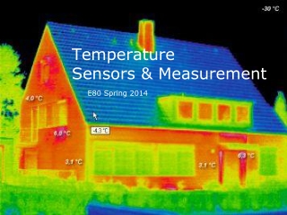
Temperature Sensors & Measurement E80 Spring 2014
Contents • Why measure temperature? • Characteristics of interest • Types of temperature sensors • 1. Thermistor • 2. RTD Sensor • 3. Thermocouple • 4. Integrated Silicon Linear Sensor • Sensor Calibration • Signal Conditioning Circuits (throughout)
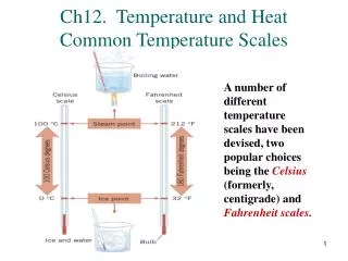
Why Measure Temperature? • Temperature measurements are one of the most common measurements... • Temperature corrections for other sensors • e.g., strain, pressure, force, flow, level, and position many times require temperature monitoring in order to insure accuracy.
Important Properties? • Sensitivity • Temperature range • Accuracy • Repeatability • Relationship between measured quantity and temperature • Linearity • Calibration • Response time
Types of Temperature Sensors? Covered Not Covered 5. Hot Wire Anemometer 6. Non-Contact IR Single Sensor 7. IR Camera 1. Thermistor Ceramic-based: oxides of manganese, cobalt , nickel and copper 2. Resistive Temperature Device -RTD Metal-based : platinum, nickel or copper 3. Thermocouple junction of two different metals 4. Integrated Silicon Linear Sensor Si PN junction of a diode or bipolar transistor 5
Part I Thermistor • High sensitivity • Inexpensive • Reasonably accurate • Lead resistance ignored • Glass bead, disk or chip thermistor • Typically Negative Temperature Coefficient (NTC), • PTC also possible • nonlinearrelationshipbetween R and T
Simple Exponential Thermistor Model • RT = R0 x exp[ β(1/T -1/T0)] • RT is the thermistor resistance (Ω). • T is the thermistor temperature (K) • Manufacturers will often give you R0, T0 and an average value for β • β is a curve fitting parameter and itself is temperature dependent.
Simple Exponential Thermistor Model • Usually T0 is room temp 25oC = 298oK • So R0 = R25 • RT = R25 x exp[β(1/T – 1/298)] • where β ≈ ln (R85/R25) /(1/358-1/298) • Not very accurate but easy to use
Better Thermistor model • Resistance vs temperature is non-linear but can be well characterised by a 3rd order polynomial • ln RT = A + B / T +C / T2 + D / T3 where A,B,C,D are the characteristics of the material used.
Inverting the equation The four term Steinhart-Hart equation T = [A1 +B1ln(RT/R0)+C1 ln2(RT/R0)+D1ln3(RT/R0)]-1 Also note: • Empirically derived polynomial fit • A, B, C & D are not the same as A1, B1 , C1 & D1 • Manufacturers should give you both for when R0 = R25 • C1is very small and sometime ignored (the three term SH eqn)
Thermistor Calibration 3-term Steinhart-Hart equation T = [A1 +B1ln(RT/R0)+D1ln3(RT/R0)]-1 How do we find A1, B1 and D1? Minimum number of data points? Linear regression/Least Squares Fit (Lecture 2)
Thermistor Problems: Self-heating • You need to pass a current through to measure the voltage and calculate resistance. • Power is consumed by the thermistor and manifests itself as heat inside the device • P = I2 RT • You need to know how much the temp increases due to self heating by P so you need to be given θ= the temperature rise for every watt of heat generated.
Heat flow • Very similar to Ohms law. The temperature difference (increase or decrease) is related to the power dissipated as heat and the thermal resistance. Δ C = P x θ • P in Watts • θ in oC /W
Self Heating Calculation • ΔoC= P x θ= (I2 RT) θDevice to ambient • Example. • I = 5mA • RT = 4kΩ • θDevice to ambient = 15 oC /W • ΔoC=
Self Heating Calculation • ΔoC= P x θ= (I2 RT) θDevice to ambient • Example. • I = 5mA • RT = 4kΩ • θDevice to ambient = 15 oC /W • ΔoC = (0.005)2 X4000 X 15 = 1.5 C
Linearization Techniques • Current through Thermistor is dominated by 10k Ωresistor.
Linearization of a 1O k-Ohm Thermistor This plot Ti = 50 0C, Ri = 275 Ω
Part II RTD • Accurate & Stable • Reasonably wide temperature range • More Expensive • Positive temperature constant • Requires constant currant excitation • Smaller resistance range • Self heating is a concern • Lead wire resistance is a concern More complicated signal conditioning
pRTD, cRTD and nRTD • The most common is one made using platinum so we use the acronym pRTD • Copper and nickel as also used but not as stable
RTD are almost linear • Resistance increases with temperature (+ slope) RT= R0(1+ α)(T –T0) • Recognized standards for industrial platinum RTDs are • IEC 6075 and ASTM E-1137 α = 0.00385 Ω/Ω/°C
Measuring the resistanceneeds a constant current source Read AN 687 for more details (e.g. current excitation circuit): http://ww1.microchip.com/downloads/en/AppNotes/00687c.pdf http://www.control.com/thread/1236021381 on 3-wire RTD
With long wires precision is a problem • Two wire circuits, • Three wire circuits and • Four wire circuits.
Two wire: lead resistances are a problem Power supply connected here No current flows in here The IDAC block is a constant current sink
Mathematical Modelling the RTD • The Callendar-Van Dusen equation RT = R0 (1 + A T + B T2 + C T3(T-100) for T < 0 oC = R0 (1+ A T + B T2) for T > 0 oC • where R0 is the resistance at T0 = 0 oC and • For platinum • A = 3.9083 x e-3 oC-1 • B = -5.775 x e-7 oC-2 • C = -4.183 x e-12 oC-4
Experimentally • Derive temperature (+/-) from the measured resistance. • Easiest way is to construct a Look-Up table inside LabView or your uP • Precision, accuracy, errors and uncertainties need to be considered.
Experimental uncertainties • For real precision, each sensor needs to be calibrated at more than one temperature and any modelling parameters refined by regression using a least mean squares algorithm. • LabView, MATLAB and Excel have these functions • The 0oC ice bath and the ~100 oC boiling de-ionised water (at sea level) are the two most convenient standard temperatures.
Part III Thermocouples • High temperature range • Inexpensive • Withstand tough environments • Multiple types with different temperature ranges • Requires a reference temperature junction • Fast response • Output signal is usually small • Amplification, noise filtration and signal processing required
Seebeck Effect Type K thermocouple
Mathematical Model • To cover all types of thermocouples, we need a 6 - 10th order polynomial to describe the relationship between the voltage and the temperature difference between the two junctions • Either • T = a0 +a1 x V + a2 x V2 +++++ a10 V10 • Or • V = b0 +b1 x T + b2 x T2 +++++ b10 T10 + αo exp(α1(T-126.9686)2) for T >0oC
One more thing… • Low voltage signal… • Long leads… • What problems could arise?
What does 8 bit accuracy mean? • Eight bits = 28-1 levels = 255 levels • Assume supply voltage between 0 and 5 volts • Minimum V step between each level ≈ 20mV • Temp range say 0 to 400 oC • Minimum temperature step ≈ 1.6 oC • This determines the quantisation error regardless the accuracy of the sensor i.e., Temp = T +/- 0.8oC
Part IV Silicon Detectors • Integrated form • -40°C to +150°C • Limited accuracy +/- 2 degree • Linear response ( no calibration is required) • Direct interface with ADC
References • Previous years’ E80 • Wikipedia • Microchip Application Notes AN679, AN684, AN685, AN687 • Texas Instruments SBAA180 • Omega Engineering www.omega.com (sensor specs, application guides, selection guides, costs) • Baker, Bonnie, “Designing with temperature sensors, part one: sensor types,” EDN, Sept 22, 2011, pg 22. • Baker, Bonnie, “Designing with temperature sensors, part two: thermistors,” EDN, Oct 20, 2011, pg 24. • Baker, Bonnie, “Designing with temperature sensors, part three: RTDs,” EDN, Nov 17, 2011, pg 24. • Baker, Bonnie, “Designing with temperature sensors, part four: thermocouples,” EDN, Dec 15, 2011, pg 24.