Download
1 / 28
290 likes | 331 Vues
Learn the basics of projection theory & methods for displaying 3D objects on 2D surfaces. Explore concepts like orthographic view, axonometric drawing, oblique projection & more. Discover how angles, distances & relationships are crucial in projection viewing.

E N D
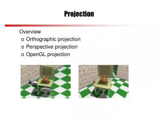
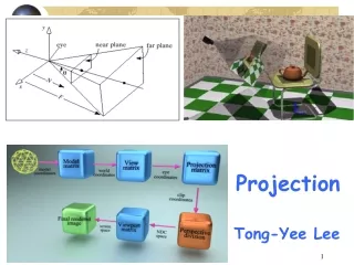
Viewing • Process for “Seeing” a world • • Projection of a 3D world onto a 2D plane • • Synthetic Camera Model • • Location of viewer and view plane • • What can be seen (Culling (picking) and Clipping) • • How relationships are maintained • Angles • Distances (Foreshortening) • Parallel Lines • Relation to Viewer
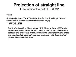
The projection theory is used to graphically represent 3-D objects on 2-D media (paper, computer screen). The projection theory is based on two variables: 1) Line of sight 2) Plane of projection (image plane or picture plane) PROJECTION THEORY
There are 2 types of LOS : Line of sight Line of sight Line of sightis an imaginary ray of light between an observer’s eye and an object. parallel converge and Parallel projection Perspective projection
The image is produced by connecting the points where the LOS pierce the projection plane. Plane of projection Plane of projection Plane of projectionis an imaginary flat plane which the image is created. Parallel projection Perspective projection
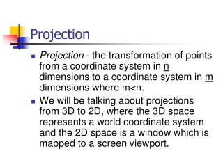
Basic definitions Projection: a transformation that maps from a higher dimensional space to a lower dimensional space (e.g. 3D->2D) Center of projection(COP): the position of the eye or camera with respect to which the projection is performed (also eye point, camera point, projection reference point) Direction of projection (DOP): the direction of an eye or camera assumed to be infinite far away. Projection plane: in a 3D->2D projection, the plane to which the projection is performed (also view plane) Projectors: lines from coordinate in original space to coordinate in projected space
Perspective Parallel Oblique Orthographic Cavalier Cabinet Axonometric Multiview 1,2,3Point PROJECTION METHOD
Object views from top 1 2 3 4 1 2 3 4 5 5 Projection plane MEANING Orthographic projectionis a parallel projection technique in which the parallel lines of sight are perpendicular to the projection plane
ORTHOGRAPHIC VIEW Orthographic view depends on relative position of the object to the line of sight. Rotate Two dimensions of an object is shown. Tilt More than one view is needed to represent the object. Multiview drawing Three dimensions of an object is shown. Axonometric drawing
Both drawing types are used in technical drawing for communication. ORTHOGRAPHIC VIEW NOTES Orthographic projection technique can produce either1. Multiview drawingthat each view show an object in two dimensions. 2. Axonometric drawingthat show all three dimensions of an object in one view.
Depth Height Depth Width Height Width Depth MULTIVIEW PROJECTION Three principle dimensions of an object … … can be presented only two in each view. Adjacent view(s) is needed tofulfill the size description.
TO OBTAIN MULTIVIEW REPRESENTATION OF AN OBJECT • Revolve the object with respect • to observer. • The observer move around the • object.
REVOLVE THE OBJECT Top view Right side view Front view
OBSERVER MOVE AROUND Top view Front view Right side view
THE GLASS BOX CONCEPT Rear view Left side view Bottom view
History Depth Width Height
Multiview Drawing Advantage It represents accurate shape and size. Disadvantage Require practice in writing and reading. Example Multiviews drawing (2-view drawing)
Axonometric & Oblique Projection
Parallel & normal to picture plane B A D C B Line of sight A D C Axonometric Projection Projection plane is not orthogonal to a principal axis
a b c B A a D c C b B a A c b D C Axonometric Projection Type of axonometric drawing Axonometric axis 1. Isometric All angles are equal, Symmetric to three faces. Axonometric axis Two angles are equal. Symmetric to two faces 2. Dimetric Axonometric axis None of angles are equal. General case 3. Trimetric
Axonometric (Isometric) Drawing Advantage Easy to understand Disadvantage Shape and angle distortion Example Distortions of shape and size in isometric drawing Circular hole becomes ellipse. Right angle becomes obtuse angle.
A A Line of sight B B C C D D Oblique Projection Parallel & oblique to picture plane Direction of projection is not orthogonal/Perpendicular to the Projection plane; Projection plane is normal to a principal axis
45o 60o A 30o B C B A D D C Full scale Half scale 45o 45o Oblique Projection Oblique drawing angle Type of Oblique drawing 1) Cavalier 2) Cabinet Cavalier: Direction of projection makes a 45° angle with the projection plane Cabinet: Direction of projection makes a 63.4° angle with the projection plane
Isometric Projection Direction of projection makes equal angles with each principal axis Rotate 45 about vertical axis Tilt forward (35o16’) All edges foreshorten about 0.8 time.
Disadvantage ofPerspective Projection Perspective projection is not used by engineer for manu- facturing of parts, because 1) It is difficult to create. 2) It does not reveal exact shape and size. But useful in animation 1) It produces the realistic view Width is distorted