Projection
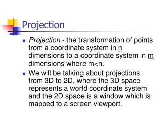
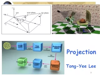
Projection. Projection. Projection. Conceptual model of 3D viewing process. Projection. In general, projections transform points in a coordinate system of dimension n into points in a coordinate system of dimension less than n .

Projection
E N D
Presentation Transcript
Projection Conceptual model of 3D viewing process
Projection • In general, projections transform points in a coordinate system of dimension n into points in a coordinate system of dimension less than n. • We shall limit ourselves to the projection from 3D to 2D. • We will deal with planar geometric projections where: • The projection is onto a plane rather than a curved surface • The projectors are straight lines rather than curves
Projection • key terms… • Projection from 3D to 2D is defined by straight projection rays (projectors) emanating from the 'center of projection', passing through each point of the object, and intersecting the 'projection plane' to form a projection.
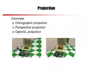
Planer Geometric Projection • 2 types of projections • perspective and parallel. • Key factor is the center of projection. • if distance to center of projection is finite : perspective • if infinite : parallel Perspective projection Parallel projection
Perspective: visual effect is similar to human visual system... has 'perspective foreshortening' size of object varies inversely with distance from the center of projection. Parallel lines do not in general project to parallel lines angles only remain intact for faces parallel to projection plane. Perspective v Parallel
Perspective v Parallel • Parallel: • less realistic view because of no foreshortening • however, parallel lines remain parallel. • angles only remain intact for faces parallel to projection plane.
Perspective projection- anomalies • Perspective foreshortening The farther an object is from COP the smaller it appears Perspective foreshortening
Perspective projection- anomalies • Vanishing Points: Any set of parallel lines not parallel to the view plane appear to meet at some point. • There are an infinite number of these, 1 for each of the infinite amount of directions line can be oriented Vanishing point
P' P 3 1 Plane containing Center of Projection (C) Y P 3 C View Plane P 2 P' 1 P' 2 X Z Perspective projection- anomalies • View Confusion: Objects behind the center of projection are projected upside down and backward onto the view-plane • Topological distortion: A line segment joining a point which lies in front of the viewer to a point in back of the viewer is projected to a broken line of infinite extent.
Vanishing Point COP View Plane Vanishing Point
Vanishing Point • If a set of lines are parallel to one of the three axes, the vanishing point is called an axis vanishing point (Principal Vanishing Point). • There are at most 3 such points, corresponding to the number of axes cut by the projection plane • One-point: • One principle axis cut by projection plane • One axis vanishing point • Two-point: • Two principle axes cut by projection plane • Two axis vanishing points • Three-point: • Three principle axes cut by projection plane • Three axis vanishing points
Vanishing Point • One point perspective projection of a cube • X and Y parallel lines do not converge
Vanishing Point • Two-point perspective projection: • This is often used in architectural, engineering and industrial design drawings. • Three-point is used less frequently as it adds little extra realism to that offered by two-point perspective projection.
VP2 VP1 VP3 Vanishing Point VPL H VPR
Projective Transformation Settings for perspective projection
Parallel projection • 2 principle types: • orthographic and oblique. • Orthographic : • direction of projection = normal to the projection plane. • Oblique : • direction of projection != normal to the projection plane.
Orthographic projection • Orthographic (or orthogonal) projections: • front elevation, top-elevation and side-elevation. • all have projection plane perpendicular to a principle axes. • Useful because angle and distance measurements can be made... • However, As only one face of an object is shown, it can be hard to create a mental image of the object, even when several view are available
Axonometric projection • Axonometric Projections use projection planes that are not normal to a principal axis.On the basis of projection planenormal N = (dx, dy, dz) subclasses are: • Isometric: | dx | = | dy | = | dz |i.e. N makes equal angles with all principal axes. • Dimetric : | dx | = | dy | • Trimetric :| dx | != | dy | != | dz |
Projection Plane Axonometric vs Perspective • Axonometric projection shows several faces of an object at once like perspective projection. • But the foreshortening is uniform rather than being related to the distance from the COP. Isometric proj
Oblique parallel projection • Oblique parallel projections • Objects can be visualized better then with orthographic projections • Can measure distances, but not angles * Can only measure angles for faces of objects parallel to the plane • 2 common oblique parallel projections: • Cavalier and Cabinet
Projection Plane Projector Projection Plane Normal Oblique parallel projection
Oblique parallel projection • Cavalier: • The direction of the projection makes a 45 degree angle with the projection plane. • There is no foreshortening
Oblique parallel projection • Cabinet: • The direction of the projection makes a 63.4 degree angle with the projection plane. This results in foreshortening of the z axis, and provides a more “realistic” view
λ sin(α) P׳(λ cos(α), λ sin(α),0) β λ α P=(0, 0, 1) λ cos(α) Oblique parallel projection • Cavalier, cabinet and orthogonal projections can all be specified in terms of (α, β)or (α, λ) since • tan(β) = 1/λ
Oblique parallel projection PP‘ = (λ cos(α), λ sin(α),-1) = DOP Proj(P) = (λ cos(α), λ sin(α),0) Generally • multiply by z and allow for (non-zero) x and y x ‘ = x + z lcos a y‘ = y + z lsin a
OpenGL’s Perspective Specification y field-of-view / fovy aspect ratio near and far clipping planes viewing frustum gluPerspective(fovy, aspect, near, far) glFrustum(left, right, bottom, top, near, far)
Perspective without Depth • The depth information is lost as the last two components are same • But dept information of the projected points is essential for hidden surface removal and other purposes like blending, shading etc.
Perspective without Depth For ß < 0, z’ is a monotonically increasing function of depth.
Canonical View Volume There is a reversal of the z- coordinates, in the sense that before the transformation, points further from the viewer have smaller z- coordinates
Perspective Matrix The matrix to perform perspective transformation: