Projection Radiography
Projection Radiography. Chapter 5 (in more detail). Projection radiography(Conventional radiography)- most common used method of medical imaging that utilizes x-rays Conventional Radiograph- represents a projection of the 3D volume of the body onto a 2D imaging surface

Projection Radiography
E N D
Presentation Transcript
Projection Radiography Chapter 5 (in more detail)
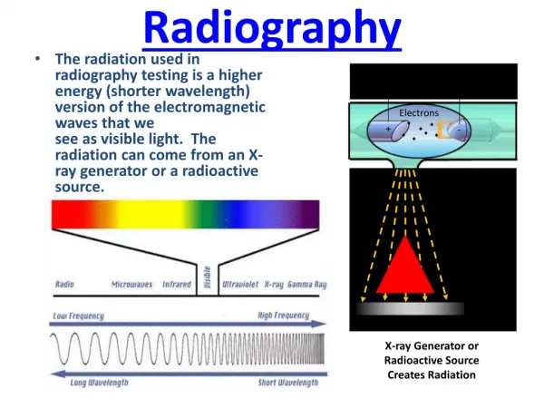
Projection radiography(Conventional radiography)- most common used method of medical imaging that utilizes x-rays • Conventional Radiograph- represents a projection of the 3D volume of the body onto a 2D imaging surface • Conceptually, the projection radiograph represents the transmission of the x-ray beam through the patient weighted by integrated loss of beam energy due to scattering and absorption in the body Introduction
Short exposure time (0.1 second) • Production of a large area image (e.g. 14x17 in.) • Low cost • Low radiation exposure(30 mR for a chest radiograph, equivalent to 1/10 of the annual background dose) • Excellent contrast and spatial resolution. Advantages of Projection Radiographic Systems
Pnemonia • Heart Disease • Lung Disease • Bone Fracture • Cancer • Vascular Disease Uses of Projection Radiography
A conventional projection radiographic system. • The X-ray generates a short pulse of x-rays as a beam that travels through the patient • X-ray photons that are not absorbed within the patient or scattered outside the region of the detector impinge upon the large area protector, ultimately creating an image on a sheet of film. Instrumentation
Filament(tungsten wire), contained within the cathode assembly, controls tube current of 6-12 volts • Anode voltage switched to high potential(30-150 kVp) • Focusing cup- small depression in the cathode containing the filament is shaped to help focus the electron beam toward a particular spot on the anode. Instrumentation
Relative intensity of x-ray photons • Vast majority of the x-rays produced by an x-ray tube are bremsstrahlung. Instrumentation
Filtration- the maximum energy of the emitted x-ray photons is determined by the tube voltage • Ex: 100 kVp is the tube voltage then the maximum photon energy is 100 keV • Low energy x-ray will be absorbed by the body without providing diagnostic info. • Inherent filtration(within anode, glass housing) • Added filtration • Restriction- to direct beam toward desired anatomy • Compensation Filters and contrast agents – used for attenuation which is the process by which x-rays are absorbed or redirected (scattered) within the body or other objects in the field of view. • Goal for Compensation: to even out film exposure • Goal for Contrast: to create contrast where there is otherwise none Instrumentation
Caused by the preferential absorption of lower energy photons, for which attenuation is higher in most materials Beam Hardening
X-ray rubes generate x-rays in all directions • Diaphragm: fixed geometry, Chest Radiography, simple and inexpensive • Cones or Cylinders: Fixed in geometry, somewhat better performance • Collimator: More expensive, Flexible and better performing , Projection X-ray systems • Collimators have variable diaphragms composed of movable piece of lead • Most often, there are two collimators, one near the tube and one farther away from the tube. Typically there is a scored mirror in between these two collimators so that a light coming from the side will shine through the second collimator, illuminating the field of view with an alignment grid. Restriction Beam
Compensation filter: comprised of a specially shaped aluminum or leaded-plastic object can be placed between the x-ray source and patient, or in some cases between the patient and detector. • The compensation filter is thicker where the body part is thinner and vice versa, so that the x-ray detector requires a smaller dynamic range. Compensation Filter
When the x-ray energy exceeds the binding energy of k-shell, the linear attenuation coefficient is much higher providing more contrast. Contrast Agents
Ideal X-ray path is a line • Compton Scattering causes blurring • Reduce Scatter: airgap, scanning slit, grid How to Reduce Scatter?
Basic Imaging Equation- the intensity of the x-rays incident on the detector at (x,y) • Geometry of a Conventional Projection Radiographic system Image Formation
Inverse Square Law states that the net flux of photons decreases as 1/r^2, where r is the distance from the x-ray origin • Example 5.2 in book. The inverse square law has a very practical use in radiography . Suppose an acceptable chest radiograph was taken using 30 mAs at 80 kVp from 1 m. Suppose that it was now requested that one be taken at 1.5 m at 80 kVp. (Show solution on board). Image Formation
Obliquity-second factor that acts to decrease the beam intensity away from the detector origin • This effect is caused by the detector not being orthogonal to the direction of x-ray propagation • Figure(below) The effect of obliquity on spot size Image Formation
Degrades image quality • Compton photons are deflected from their ideal straight-line path and some are detected in locations away from the correct, straight-line location----this produces two unwanted results: decrease in image contrast and a decrease in SNR Compton Scattering(cont.)
Projection radiography produces radiographs which are 2-D projections of a 3D object • EA projection radiography system consists of an x-ray tube, devices for beam filtration and restriction, compensation filters, grids and usually a film-screen protector. • The basic imaging equation describes the energy and material-dependent attenuation of the x-ray beam produced by the system as it passes through the patient • This equation must be modified by several geometric effects, including square law, obliquity, divergence, anode heel effect, path length, and depth-dependent magnification. • The film screen protector produces an optical image on film; the degree of film blackening- the optical density- depends on film exposure in a nonlinear way characterized by the H&D curve • Noise arising from the random nature of x-ray production and transmission reduces an image’s signal-to-noise- ratio and thus the detective quantum efficiency of the sytem. • Acceptance of the Compton Scattered photons reduces image contrast and thus signal-to-noise ratio as well. Summary