Download
1 / 26
390 likes | 565 Vues
This guide introduces orthographic projections, which are essential in technical drawing. It explains the significance of the six principal views in representing an object accurately. Following guidelines on selecting the most descriptive front view, the text highlights the glass box approach to visualize different perspectives effectively. The document covers line types, thickness, dimensioning techniques, and tolerancing standards crucial for creating detailed engineering drawings. Additionally, it emphasizes the importance of a well-organized drawing layout, including necessary title block information.

E N D
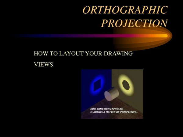
ORTHOGRAPHIC PROJECTION AN INTRODUCTION
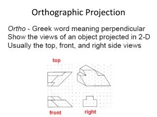
Orthographic Projections • Orthographic Projections are a collection of 2-D drawings that work together to give an accurate overall representation of an object.
Defining the Six Principal Views or Orthographic Views (111rd Angle)
Which Views to Present? General Guidelines • Pick a Front View that is most descriptive of object • Normally the longest dimension is chosen as the width (or depth) • Most common combination of views is to use: • Front, Top, and Side View
Glass Box Approach • Place the object in a glass box • Freeze the view from each direction (each of the six sides of the box) and unfold the box
Third-angle Projection First-angle Projection First and Third Angle Projections • First Angle • Third Angle
Width Top View/Plan Depth Right Side View Front View Height Conventional Orthographic Views(111rd Angle)
Lines on an engineering drawing signify more than just the geometry of the object and it is important that the appropriate line type is used. Line Thickness For most engineering drawings you will require two thickness', a thick and thin line. The general recommendation are that thick lines are twice as thick as thin lines. Line Styles Other line styles used to clarify important features on drawings are:
0.6 mm 0.3 mm 0.6 mm Precedence of Lines • Visible lines takes precedence over all other lines • Hidden lines and cutting plane lines take precedence over center lines • Center lines have lowest precedence
For Example: 1. Visible 2. Hidden 3. Center
Dimensioning A dimensioned drawing should provide all the information necessary for a finished product or part to be manufactured. An example dimension is shown below. Dimensions are always drawn using continuous thin lines. Two projection lines indicate where the dimension starts and finishes. Projection lines do not touch the object and are drawn perpendicular to the element you are dimensioning. All dimensions less than 1 should have a leading zero. i.e. .35 should be written as 0.35
Types of Dimensioning • Parallel Dimensioning • Parallel dimensioning consists of several dimensions originating from one projection line.
Superimposed Running Dimensions • Superimposed running dimensioning simplifies parallel dimensions in order to reduce the space used on a drawing. The common origin for the dimension lines is indicated by a small circle at the intersection of the first dimension and the projection line.
Chain Dimensioning • Combined Dimensions • A combined dimension uses both chain and parallel dimensioning.
Dimensioning of circles • (a) shows two common methods of dimensioning a circle. One method dimensions the circle between two lines projected from two diametrically opposite points. The second method dimensions the circle internally. • (b) is used when the circle is too small for the dimension to be easily read if it was placed inside the circle.
Dimensioning Radii • All radial dimensions are proceeded by the capital R. • shows a radius dimensioned with the centre of the radius located on the drawing. • (b) shows how to dimension radii which do not need their centres locating.
Tolerancing • It is not possible in practice to manufacture products to the exact figures displayed on an engineering drawing. The accuracy depends largely on the manufacturing process. A tolerance value shows the manufacturing department the maximum permissible variation from the dimension. • Each dimension on a drawing must include a tolerance value. This can appear either as: • a general tolerance value applicable to several dimensions. i.e. a note specifying that the General Tolerance +/- 0.5 mm. • or a tolerance specific to that dimension
Drawing layout All engineering drawings should feature a title block. The title block should include: Title:- title of the drawing Name:- name of the person who produced the drawing Checked:- before manufacture, drawings are usually checked Version:- many drawings are amended, each revision must be noted Date:- the date the drawing was produced or last amended Notes:- any note relevant to the drawing Scale:- the scale of the drawing Company name:- name of the company Projection:- the projection system used to create the drawing