8 . Fault Tolerance in Software
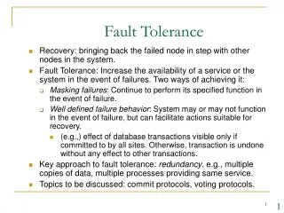
8 . Fault Tolerance in Software. 8.4 Design of Fault Tolerant Software Using Diversity 8.4. 3 The Distributed Recovery Block. The Distributed Recovery Block (DRB) was formulated as a means of integrating HW and SW fault tolerance in a single structure.

8 . Fault Tolerance in Software
E N D
Presentation Transcript
8. Fault Tolerance in Software 8.4 Design of Fault Tolerant Software Using Diversity • 8.4.3 The Distributed Recovery Block The Distributed Recovery Block (DRB) was formulated as a means of integrating HW and SW fault tolerance in a single structure. It is a modification of the Recovery Block Technique. The difference is that in the DRB the primary and alternate routines are both replicated and are resident on two or more nodes interconnected by a network.
8. Fault Tolerance in Software 8.4 Design of Fault Tolerant Software Using Diversity • 8.4.3 The Distributed Recovery Block In the attempt of a failure of the primary node as detected by the acceptance test, the primary node attempts to inform the backup node of the failure. When the backup node receives notice, it assumes the role of the primary node. Because it has been processing the alternate routine concurrently, a result will generally be immediately available for output. Thus, the recovery time for this type of failure is much shorter than if both try blocks were running on the same node (i.e., as in the Recovery Block Technique presented previously).
8. Fault Tolerance in Software 8.4 Design of Fault Tolerant Software Using Diversity • 8.4.3 The Distributed Recovery Block If the primary node stops processing entirely (due to a hang in the application, a crash of the OS or on the HW), no update message will be passed to the backup node which detects the crash by means of expiration of a local timer which constitutes the time acceptance test. This is the key to the integration of HW and SW FT.
8. Fault Tolerance in Software 8.4 Design of Fault Tolerant Software Using Diversity • 8.4.3 The Distributed Recovery Block • Distributed • Recovery block.
8. Fault Tolerance in Software 8.4 Design of Fault Tolerant Software Using Diversity • 8.4.4 The Extended Distributed Recovery Block Next figure shows a top-level diagram of a typical EDRB configuration which consists of dual redundant processors which are interconnected by dual redundant networks. Members of a node pair exchange periodic status messages called heartbeats. A member in a node pair is capable of recovering from failures in its companion if a malfunction has been declared as part of the heartbeat message. If a node does sense the absence of its companion heartbeat, it requests confirmation of the failure from the network supervisor.
8. Fault Tolerance in Software 8.4 Design of Fault Tolerant Software Using Diversity • 8.4.4 The Extended Distributed Recovery Block The supervisor (a non-redundant processor) which confirms the absence of a heartbeat, arbitrates the inconsistent states in the node pairs, and logs all status changes and failures. Although the supervisor is important to the EDRB operation, the node is not critical because its failure only impacts the ability of the system to recover from failures requiring its confirmation and arbitration.
8. Fault Tolerance in Software 8.4 Design of Fault Tolerant Software Using Diversity • 8.4.4 The Extended Distributed Recovery Block • Structure of the EDRB.
8. Fault Tolerance in Software 8.4 Design of Fault Tolerant Software Using Diversity • 8.4.4 The Extended Distributed Recovery Block A simplified view of the SW structure in a node pair and its interaction with the supervisor is shown in the next figure. Nodes in a pair employ active redundancy. One node is always active, the other is the shadow (i.e., standby). Under normal circumstances, the active node executes the primary version of a control task in parallel with an alternate version executed on the shadow node.
8. Fault Tolerance in Software 8.4 Design of Fault Tolerant Software Using Diversity • 8.4.4 The Extended Distributed Recovery Block In the acceptance test of the active node is not passed, the active node might request the shadow node to promote itself to active and immediately send out its result to minimize recovery time. When a node fails to issue a heartbeat, an EDRB SW component called monitor task in the companion node requests permission from the supervisor to assume control if it is not in the active role. If the supervisor concurs that a heartbeat is absent, consent is transmitted and the shadow node promotes itself as if the failure were announced by the companion node. Next, the shadow node initiates a HW reset of the node from which the heartbeat message was not received.
8. Fault Tolerance in Software 8.4 Design of Fault Tolerant Software Using Diversity • 8.4.4 The Extended Distributed Recovery Block The time interval between heartbeats is called a frame, and is typically set at 0.020 seconds (on a 33MHz Intel 80486-based PC/AT compatible computer).
8. Fault Tolerance in Software 8.4 Design of Fault Tolerant Software Using Diversity • 8.4.4 The Extended Distributed Recovery Block • Software structure of the EDRB.