Download
1 / 64
640 likes | 690 Vues
Explore the historical progression and changes in computer architecture, from the emergence of microprocessors to the latest advancements in instruction set design. Learn about key concepts such as RISC architecture, ILP, caches, and addressing modes.

E N D
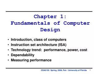
Fundamentals of Computer Design Chapter 1 Dr. Anilkumar K.G (SC6231)
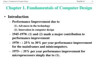
Introduction (1) • Computer technology has made incredible progress in 60 years since first general-purpose electronic computer was created • The late 1970s has shown the emergence of microprocessor with- • Improvement in IC technology • 35% growth per year in performance Dr. Anilkumar K.G (SC6231)
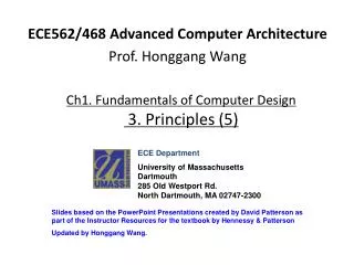
Introduction(2) • There are significant changes in microprocessor-based computer architecture: • Virtual elimination of Assembly Language programming • Creation of vender independent OSs such as UNIX, Linux, etc • RISC architecture (in early 1990s) • Exploitation of Instruction Level Parallelism (ILP) • Use of Caches • Figure 1.1 shows the growth in processor performance since the mid-1980s Dr. Anilkumar K.G (SC6231)
Introduction(3) Figure 1.1 Growth in processor performance since the mid-1980s Dr. Anilkumar K.G (SC6231)
Introduction (4) • Since 2002, processor performance improvement has dropped 20% due to • Power dissipation of air cooled chips • Little ILP • Unchanged memory latency • In 2004 Intel cancelled its high-performance uni-processor projectand joined IBM and SUN for multiple processor per chip project • This signals the following: • ILP (Instruction Level Parallelism) • TLP (Thread Level Parallelism) • DLP(Data Level Parallelism) Dr. Anilkumar K.G (SC6231)
Task of a Computer Architecture • Task of a computer designer is very complex: • Determine what attributes are important for a new computer • Then design a computer to maximize performance while staying within cost, power, and available constraints • Including ISA (Machine language), functional organization, logic design, and implementation • The implementation covers IC design, packaging, power and cooling • Optimizing the design requires familiarity with a wide range of technologies • From compilers and OS to logic design and packaging Dr. Anilkumar K.G (SC6231)
Computer Architecture- In the Past • In the past, the term computer architecture often referred only to instruction set design • And other aspects of computer design were called implementation • In reality: The architect’s or designer’s job is much more than instruction set design! Dr. Anilkumar K.G (SC6231)
Instruction Set Architecture (1) • The term instruction set architecture (ISA) refers to the programmer /compiler designer visible instruction set (part of control unit of the CPU/processor and is also referred as “micro ISA”) • The ISA serves as the boundary between the SW (software) and HW (hardware) • A quick review of ISA (examples from MIPS and Intel x86) illustrated here and a detailed version will be studied later • In this course, we focus details of a MIPS (Microprocessor without Interlocked Pipeline Stages) system and is invented in 1981by a team led by Prof. John L. Hennessy at Stanford University Dr. Anilkumar K.G (SC6231)
Instruction Set Architecture(2) • Class of ISA • Current ISAs are classified as general-purpose register(GPR) architecture (operands are either registers or memory) • Intel 80x86 has 16 GPRs and that can hold floating point (FP) data • MIPS has 32 GPRs and 32 FP registers (Figure 1.2) • These two ISAs are register-memory architectures: • Intel 80x86 accesses memory as part of move instructions • MIPS accesses memory only with load/store instructions Dr. Anilkumar K.G (SC6231)
Instruction Set Architecture(3) Dr. Anilkumar K.G (SC6231)
Instruction Set Architecture(4) • Memory Addressing • Virtually all computers including the x86 and MIPS use byte addressing to access memory operands • MIPS requires that objects must be aligned (Figure 1.3 shows addresses aligned and misaligned). • An access to an object of size larger than a byte must be aligned • Misalignment causes HW complications • Programs with aligned access run faster • 80x86 does not require alignment, instruction accessesare faster if operands are aligned Dr. Anilkumar K.G (SC6231)
Instruction Set Architecture(5) • Addressing modes • Addressing modes specify registers, constant operands, and address of a memory object • MIPS’saddressing modes are registers, immediate (for constants), and displacement • 80x86 supports the above three plus further three different displacements modes: • No register (absolute), • Two registers (based indexed with displacement) Dr. Anilkumar K.G (SC6231)
Addressing Modes Dr. Anilkumar K.G
Instruction Set Architecture(6) • Types and sizes of operands • MIPS and Intel x86 support operand sizes of • 8-bit (ASCII character) • 16-bit (half word) • 64-bit (double word or long integer) • IEEE 754 FP in 32-bit ( single precision) and 64-bit (double precision) • Intel x86 also supports 80-bit FP (for extended double precision) Dr. Anilkumar K.G (SC6231)
Instruction Set Architecture(7) • Operations • The general categories of operations are; • Data transfer, arithmetic logic, and FP • MIPS is a simple and easy-to-pipeline ISA and is the representative of the RISC (Reduced Instruction Set Computer) architecture • Intel x86 has richer and larger set of operations and is CISC (Complex Instruction Set Computer)architecture) Dr. Anilkumar K.G (SC6231)
Instruction Set Architecture(8) • Control flow instructions • All ISAs (including both MIPS and Intel x86) support conditional branches, unconditional jumps, procedure calls, and returns • And use PC (program counter)-relative addressing • Where the branch address is specified by an address field that is added to the contents of the PC • MIPS conditional branchtest the contents of registerswhile in Intel x86, branch test is based on condition code bits(called flags) • MIPS procedure call places the return address in a register(supported by register window) • Intel x86 procedure call places the return address on a stack memory location Dr. Anilkumar K.G (SC6231)
Instruction Set Architecture(9) • Encoding an ISA • There are two basic choices on encoding ISA • Fixed length and • variable length • All MIPS instructions are 32-bit long (fixed) which simplifies instruction decoding RISC (Figure 1.4) • Intel x86 encoding is variable length, ranging from 1 to 18 bytes CISC architecture • Variable length instructions can take less space than fixed-length instructions • Program compiled for Intel x86 smaller than the same program compiled for MIPS Dr. Anilkumar K.G (SC6231)
Instruction Set Architecture(10) Dr. Anilkumar K.G (SC6231)
Computer Architecture: Organization and HW to Meet Goals and Requirements • The implementation of a computer has two components: • Organization: includes high-level aspects of a computer’s design such as memory, processors, etc • For example, 2 processors with same ISA but vary with different organizations are AMD Optron 64 and Intel Pentium 4 • Both processors implement the x86 ISA, but different pipeline and cache organizations Dr. Anilkumar K.G (SC6231)
Computer Architecture: Organization and HW to Meet Goals and Requirements • Hardware implementation • HW refers to the specifics of a computer (including detailed logic design and the packaging technology) • Identical organizations differ in HW details • Pentium 4 and Mobile Pentium 4 are nearly identical but different clock rates and different memory systems • Figure 1.5 shows summary of some of the most important functional requirements an architect faces Dr. Anilkumar K.G (SC6231)
Trends in Technology • Four implementation technologies, which changes at a dramatic pacecritical to modern computer implementations are: • IC logic technology: Transistor density increases by about 35% per year (Moore’s Law) • Increases in semiconductor-die size ranging from 10% to 20% per year • A growth rate in transistor count on a chip of about 40-55% • DRAM: Capacity increases by about 40% per year, doubling roughly every two years • Magnetic Disk: Disk density increased by about 30% per year, doubling in three years • Network technology: Improvements in switching speed Dr. Anilkumar K.G (SC6231)
Performance Trends: Bandwidth over Latency • Bandwidth or Throughput is the total amount of work done in a given time • Such as megabytes per second for a disk transfer • Latency or Response time is the time between the start and the completion of an event • Such as milliseconds for a disk access • Figure 1.6 shows the relative improvement in BW and latency for processors, memory, networks and disks Dr. Anilkumar K.G (SC6231)
Integrated Circuit (IC) Dr. Anilkumar K.G (SC6231)
Trends in Power in ICs (1) • For CMOS chips, the traditional dominant energy consumption has been in switching transistors, called dynamic power(powerdynamic) in watt • The powerdynamic per transistor is proportional to the product of the load capacitance of the transistor, square of the voltage, and the switching frequency: Powerdynamic = ½ x load capacitance x voltage2 x frequency switched • Mobile devices care about battery life than power, so energy Energydynamic = load capacitance x voltage2 • Today's challenge: distributing the power, removing heat of the microprocessor • Most processors today turn off the clock of inactive module to save energy Dr. Anilkumar K.G (SC6231)
Trends in Power in ICs(2) • Some microprocessors today are designed to have adjustable voltage, so that a 15% reduction in voltage may result in a 15% reduction in frequency. What would be the impact on dynamic power? Since the load capacitance unchanged, the answer is the ratios of the voltages and frequencies. Powernew = (voltage x 0.85)2 x (Frequency switched x 0.85) Powerold (voltage)2 x (Frequency switched) = 0.853 = 0.61 Thereby reducing power to about 61% of the original Dr. Anilkumar K.G (SC6231)
Cost of IC (1) • Although the costs of the ICs dropped exponentially, the basic process of silicon manufacturer is unchanged: • A silicon wafer is still tested and chopped into dies that are packaged (Figure 1.7 shows example wafer) Cost of the IC = (cost of die + cost of die test + cost of package and final test)/Final test yield Cost of die = Cost of wafer / (die per wafer x die yield) Dies per wafer = Where r2 is the wafer area, d is the wafer circumference Dr. Anilkumar K.G (SC6231)
Cost of IC (2) Die yield = Wafer yield (1 + ([ X* Die area]/)) - Where is a complexity parameter with a good estimate 4.0 and X = Defects/unit area. Dr. Anilkumar K.G (SC6231)
Cost of IC(3) • Find the no. of dies per 30 cm wafer for a die that is 1.5 cm on a side. • Find the die yield for two dies that are 1.5 cm on a side and 0.7 cm on a side, assuming a defect density of 0.4 per cm2 and is 4 (assume that in both cases wafer yield is 1). Dr. Anilkumar K.G (SC6231)
Cost Trends for Processors Dr. Anilkumar K.G (SC6231)
Dependability(1) • How to decide when a system is operating properly? • Infrastructure providers offer Service Level Agreements (SLA) to guarantee that the networking or power service would be dependable • Systems alternate between two states of service with respect to an SLA: • Service accomplishment, where the service is delivered as specified in SLA • Service interruption, where the delivered service is different from the SLA • Failureis transition from state 1 to state 2 and Restorationis transition from state 2 to state 1 Dr. Anilkumar K.G (SC6231)
Dependability (2) • Important Metrics • Module reliability= measure of service continuation(or time to failure) • Mean Time To Failure (MTTF) measures Reliability • Failures In Time (FIT) =1/MTTF, the rate of failures • Traditionally reported as failures per billion hours of operation • Mean Time To Repair(MTTR) measures Service Interruption • Mean Time Between Failures (MTBF)= MTTF+ MTTR • Module availability measures service as alternate between the 2 states of accomplishment and interruption (number between 0 and 1, e.g. 0.9) • Module availability = MTTF /(MTTF + MTTR) Dr. Anilkumar K.G (SC6231)
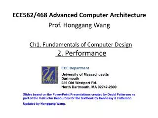
Measuring Performance • Response time: time between start and completion of an event (execution time) • Throughput: total amount of work done in a given time • "X is n times faster than Y” means Execution Time (Y)=n=Performance(X) Execution Time (X) Performance (Y) • CPU time (Execution time) • User CPU time: CPU time spent in the user program • System CPU time: CPU time spent in the OS tasks Dr. Anilkumar K.G (SC6231)
How to Summarize Performance (1) • Arithmetic mean tracks execution time: Where Ti is the execution time for the ith program of a total of n workload Wi is the weight of i operations,W1 + W2 +…+ Wn= 1 Dr. Anilkumar K.G (SC6231)
How to Summarize Performance(2) • Harmonic mean (weighted harmonic mean) of rates: Where Ri = 1/Ti • Weights indicates unequal mix of loads Dr. Anilkumar K.G (SC6231)
How to Summarize Performance(3) • Ex. Consider the example in the subsection on arithmetic means of jobs being run on the corporate computer. We express the observations in a rate measure of jobs per hour. These data are 0.5, 0.45, 0.53 and 0.43 jobs per hour. What is the central tendency of these measurements in jobs per hour? • Ans: Dr. Anilkumar K.G (SC6231)
How to Summarize Performance (4) • Some data observations are ratios of either times or rates. The geometric mean is the central tendency of ratios Ratio: execution time ratio Dr. Anilkumar K.G (SC6231)
How to Summarize Performance (5) • Ex. Two computers execute four loops of scientific program in the number of clocks shown below. What is the central tendency of the speedup for the loops (A to B)? Dr. Anilkumar K.G (SC6231)
Which Machine is “Better”? • Computer AComputer BComputer C • Program P1(sec) 1 10 20 • Program P2 1000 100 20 • Total Time 1001 110 40 • A is ---------- times faster than B for program P1. • B is ---------- times faster than A for program P2. • A is ----------times faster than C for program P1. • C is --------- times faster than A for program P2. • B is --------- times faster than C for program P1. • C is --------- times faster than A for program P1 and P2. • B is -------- times faster than A for programs P1 and P2. Dr. Anilkumar K.G (SC6231)
Take Advantage of Parallelism (1) • Parallelism is the most important method for improving performance • From an individual processor, taking advantage of parallelism among instructions is critical • One simplest way to achieve this through pipelining (you will study pipelining later) • Pipelining is a way to reduce the total time to complete an instruction sequence by overlapping the execution of instructions • In pipelining, not every instruction depends on its immediate predecessor • Thus in a pipelined machine, executing the instructions completely or partially in parallel Dr. Anilkumar K.G (SC6231)
Take Advantage of Parallelism(2) • Parallelism can also be exploited at the level of digital design • Set-associative caches (will study later) use multiple banks of memory that are searched in parallel to find a desired item • Modern ALUs use carry-look ahead, which supports parallelism to speed the process of computing sums from linear to logarithmic values Dr. Anilkumar K.G (SC6231)
Principle of Locality • Principle of locality: programs tend to reuse data and instructions they have used recently • Rule of thumb – a program spends 90%of its execution time in only 10% of the code (re-using of instructions!) • An implication of locality is that we can predict with reasonable accuracy what instruction and data will use in the near future based on its past accesses • Two different types of locality: • Temporal locality states that recently accessed items are likely to be accessed in the near future (e.g., subroutine call or loop execution) • Spatial locality says that items whose addresses are near one another tend to be referenced close together in time (e.g. Normal program execution, sequential) Dr. Anilkumar K.G (SC6231)
Amdahl’s Law(1) • Amdahl’s law states that the performance gain can be obtained by improving some portion of a computer • The performance improvement to be gained from using some faster mode of execution is limited by the fraction of the time the faster mode can be used • Amdahl’s law defines the speedup that can be gained by using a particular feature: Speedup=Performance for entire task with enhancement Performance for entire task without using the enhancement Speedup = Execution time for entire task without the enhancementExecution time for entire task with enhancement • Speedup will tell us how much faster a task will run using enhancement Dr. Anilkumar K.G (SC6231)
Amdahl’s Law(2) • Speedup of Amdahl’s law depends on two factors: • The fraction of the computation time (Fractionenhanced) in the original computer that can be converted to take advantage of the enhancement. • The improvement gained by the enhanced mode; how much faster the task run if the enhancement where used for the entire program (Speedupenhanced). Dr. Anilkumar K.G (SC6231)
Amdahl’s Law (3) ExTimenew = ExTimeold x (1 - Fractionenhanced) + Fractionenhanced Speedupenhanced 1 ExTimeold ExTimenew Speedupoverall = = (1 - Fractionenhanced) + Fractionenhanced Speedupenhanced Dr. Anilkumar K.G (SC6231)
Amdahl’s Law (4) • Assume that a program has two components, t1 and t2. The component t2 can be speeded up. The fraction of time that can be speeded by a factor n. Then the overall speedup of the system is: speedup = (t1 + t2) / [t1 + (t2/n)](1) • For some problems, we may not know the values of t1 and t2. We define a to be the fraction of time that cannot be speedup and (1-a) as the fraction of time that can be speeded up by a factor n. Then the speedup can be calculated as: t1 + t2 = 1 (2) a = t1/(t1 + t2) = t1 (3) Dr. Anilkumar K.G (SC6231)
Amdahl’s Law (5) (1 – a) = t2 /(t1 + t2) = t2 (4) Hence apply a and (1 – a) into equation ( 1) we get: speedup = 1/(a + (1 – a)/n) (5) • Incase, a is the fraction of time that can be speeded up, then show the Amdahl’s law: The solution is, substitute a for (1 – a) and (1 – a) for a into equation (5): speedup = 1 /((1 – a) + a / n) (6) Where a is fraction of time enhanced for speedup. Dr. Anilkumar K.G (SC6231)