Download
1 / 25
260 likes | 338 Vues
Explore the various phases of combustion in Diesel Engines, from Premixed to Diffusion Combustion, Post Injection, and Emission Norms along with key factors affecting efficiency and emissions.

E N D
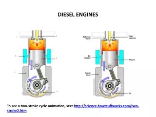
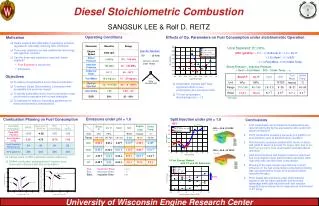
Combustion in Diesel Engines P M V Subbarao Professor Mechanical Engineering Department Special Behavioral Issues of Teen Combustion ….
Occurrence of Process in CI Engines Start of injection End of injecction -10
Homogeneous Combustion in CI Engine Premixed combustion phase (bc) – combustion of the fuel which has mixed with the air to within the flammability limits (air at high-temperature and high-pressure) during the ignition delay period occurs rapidly in a few crank angles. Start of injection End of injecction 10 30 -20 -10 TC 20
Premixed combustion • It is assumed that the rate of premixed combustion is proportional to the mass of the fuel-air mixture prepared during the ignition delay period and given as where is the Taylor microscale and Sl is the laminar flame speed. mmix,jis the mass of the fuel-air mixture in the given element. Cp is an arbitrary tuning constant determined to (0.002 to 0.005) to match the test bed data.
The Taylor microscale • The Taylor microscale is given as where u' is the rms value of turbulent fluctuation velocity, L is the integral length scale, and is the kinematic viscosity. The constant, A, is set to be close to unity. The integral length scale is given as where the constant, Cv, is in the range of 0.06 – 0.12.
Mixing controlled combustion phase (cd) – after premixed gas consumed, the burning rate is controlled by the rate at which mixture becomes available for burning. • The burning rate is controlled primarily by the fuel-air mixing process. Start of injection End of injecction 10 30 -20 -10 TC 20
Diffusion combustion • Fuel-air mixing is the dominant mechanism to determine the rate of combustion during the diffusion combustion period.
Diffusion combustion • Fuel-air mixing is the dominant mechanism to determine the rate of combustion during the diffusion combustion period. • The turbulent mixing time scale is introduced to represent the rate of fuel-air mixing as,
where mb; and me are the masses of burned fuel and entrained air in the element. • The time scales, c and ca, denote the mixing time and the time corresponding to one degree crank angle. • The arbitrary tuning constant, Ce, is chosen here to be 3.0 -- 5.0 X 10⁻⁵ to match the test bed data.
Post Injection Combustion • The models during the fuel injection period may not be applicable after the end of fuel injection for the spray detached from the nozzle and moving downstream. • The in-cylinder flow effects need to be considered to predict the combustion after the end of fuel injection. • This is described as a mixing process with the available air at a rate controlled by turbulence in the fuel jet as, where meais the total mass of unused air in the cylinder. The constant, Ce,a, is determined from the continuity of the combustion rate at the end of fuel injection.
Post (End of ) Injection Combustion • The models during the fuel injection period may not be applicable after the end of fuel injection for the spray detached from the nozzle and moving downstream. • The in-cylinder flow effects need to be considered to predict the combustion after the end of fuel injection. • This is described as a mixing process with the available air at a rate controlled by turbulence in the fuel jet as, where meais the total mass of unused air in the cylinder. The constant, Ce,a, is determined from the continuity of the combustion rate at the end of fuel injection.
Late combustion phase (de) – heat release may proceed at a lower rate well into the expansion stroke (no additional fuel injected during this phase). • Combustion of any unburned liquid fuel and soot is responsible for this. Start of injection End of injecction 10 30 -20 -10 TC 20
Hydrocarbon Emission Sources for CI Engines Overmixing of fuel and air - During the ignition delay period evaporated fuel mixes with the air, regions of fuel-air mixture are produced that are too lean to burn. Some of this fuel makes its way out the exhaust. Longer ignition delay more fuel becomes overmixed. Undermixing of fuel and air - Fuel leaving the injector nozzle at low velocity, at the end of the injection process cannot completely mix with air and burn.
Effect of Ignition Delay on HC Emissions in CI Engine Exhaust HC, ppm
Formation of CO in CI Engines • The mean air-fuel mixture present in the combustion chamber per cycle is far leaner in the diesel engine than in the SI engine. • Due to a lack of homogeneity of the mixture built up by stratification, however, extremely “rich” local zones are exist. • This produces high CO concentrations that are reduced to a greater or lesser extent by post-oxidation. • When the excess-air ratio increases, dropping temperatures cause the post-oxidation rate to be reduced. • The reactions “freeze up”. • However, the final CO concentrations of diesel engines therefore are far lower than in SI engines. • The basic principles of CO formation, however, are the same as in SI engine.
Particulates • A high concentration of particulate matter (PM) is manifested as visible smoke in the exhaust gases. • Particulates are any substance other than water that can be collected by filtering the exhaust, classified as: • Solid carbon material or soot. • Condensed hydrocarbons and their partial oxidation products. • Diesel particulates consist of solid carbon (soot) at exhaust gas temperatures below 500oC, HC compounds become absorbed on the surface. • In a properly adjusted SI engines soot is not usually a problem . • Particulate can arise if leaded fuel or overly rich fuel-air mixture are used. • Burning crankcase oil will also produce smoke especially during engine warm up where the HC condense in the exhaust gas.
Mechanism of Formation of Particulates (soot) The soot formation process is very fast. 10 – 22 C atoms are converted into 106 C atoms in less than 1 ms. Based on equilibrium the composition of the fuel-oxidizer mixture soot , formation occurs when x ≥ 2a (or x/2a ≥ 1) in the following reaction: Experimentally it is found that the critica C/O ratio for onset of soot formation is between 0.5 and 0.8. The CO, H2, and C(s) are subsequently oxidized in the diffusion flame to CO2 and H2O via the following second stage. Any carbon not oxidized in the cylinder ends up as soot in the exhaust!
NOx Formation in I.C. Engines Three chemical reactions form the Zeldovich reaction are: Forward rate constants: Zelodvich reaction is the most significant mechanism of NO formation in IC engines.
Global Reaction Rate • Using the chemical reactions given, one can write the following expression for the rate of change of nitric oxide concentration. • Where the brackets denote concentrations in units of molecules/m3. • Approximations to solve above equation: • The C-O-H system is in equilibrium and is not perturbed by N2 dissociation. • This means that the pressure, temperature, equivalence ratio and residual fraction of fluid element only are required to calculate NO concentration. • N atoms change concentration by a quasi-steady process. • This means that one can solve for the N atom concentration by setting the rate of change of atoms to zero.
Emissions Control • Three basic methods used to control engine emissions: • 1)Engineering of combustion process -advances in fuel injectors, oxygen sensors, and on-board computers. • 2) Optimizing the choice of operating parameters -two Nox control measures that have been used in automobile engines are spark retard and EGR. • 3) After treatment devices in the exhaust system -catalytic converter.