Download
1 / 19
190 likes | 264 Vues
Fuel induction systems play a crucial role in enhancing the performance of spark-ignition engines by ensuring a homogeneous mixture of air and fuel. This article discusses the importance of modern fuel injection systems like the Multi-Point Fuel Injection (MPFI) and how they help in achieving better volumetric efficiency, uniform fuel distribution, and precise control of the equivalence ratio. It also touches upon the evolution of electronic fuel injection systems, specifically Port Fuel Injection (PFI), and highlights the significance of controlling wall wetting in port injection for optimal engine performance. The integration of multi-physics processes modeling has further advanced fuel induction systems, providing more insights into engine behavior. Understanding the anatomy of EFI solenoid magnets is also crucial in comprehending the functioning of these sophisticated systems.

E N D
Fuel Induction Systems for S.I. Engines P M V Subbarao Professor Mechanical Engineering Department Hardware to Satisfy the Needs of Otto Cycle.…...
Reversible Subsonic Flow Nozzle : Venturi pthroat p1 = p2s > pthroat p1 p1 p2s p
Real Flow Through A Venturi pthroat p2a < p2s p1 p1 p2s p p2a
Actual Air Flow Through Venturi Where Fuel Flow Through Orifice
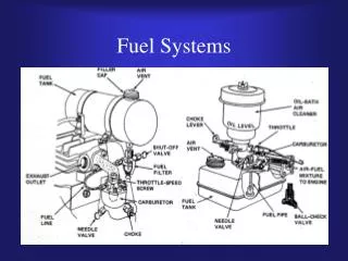
Need for Fuel Injection in SI Engine • One of the main factors to achieve near complete combustion and better engine performance is the generation of a homogenous mixture of air and fuel in the cylinder. • The most of fuel should evaporate in the ports and mix with the inlet air. • Formation a liquid fuel layers at the port and the cylinder walls should be minimized. • The better solution is injection of fuel even in in the inlet port of gasoline (SI) vehicles using MPFI system.
Artificial Induction of Fuel • The fuel-induction systems for current (high percentage) spark-ignition engines inject the fuel. • There are both mechanical and electronically controlled injection systems. • Helps in achieving better volumetric efficiency • More uniform fuel distribution • More rapid response to changes in loading conditions • More precise control of the equivalence ratio.
The Need for Multi Physics Processes Modeling in Port Injection Large-scale introduction of Port Fuel Injection (PFI) in the mid-1980s. Metered fuel is introduced into each engine intake runner individually with a low-pressure, port fuel injector, by means of a brief injection event during each engine cycle. Early dynamometer tests indicated that numerous engine performance and emission parameters were significantly influenced by both; the cone angle of the spray plume and its direction relative to the back face of the intake valve.
Anatomy of EFI Solenoid Magnet