Manufacturing Challenges of Large Superconducting Coil for Linear Collider Detector
Explore winding and manufacturing issues of a superconducting coil for Linear Collider Detector, discussing conductor types, bending challenges, winding techniques, and modular structures. Learn about different winding methods and considerations for successful coil construction.

Manufacturing Challenges of Large Superconducting Coil for Linear Collider Detector
E N D
Presentation Transcript
Coil winding issues Based on experience acquired with CMS coil construction, some preliminary considerations about the envisaged winding (and in general manufacturing) issues of a large superconducting coil for the Linear Collider Detector is presented.
The magnet for LCD include a sc coil with: Large bore ID from 5.2 m to 7.2 m Length from 6 m to 7.5 m Many layers.. 6 ..of stiff conductor . Many ideas about a CMS type conductor, but other possibilities based on cable in conduit can not be presently excluded. Which kind of manufacturing problems are to be faced depending on the different choices?
Let’s consider two cases for a coil 5.2÷7.2 m ID, 7.5 m length and 6 layers with conductor: • A CMS type. Not going into details it has dimensions 22 mm × 64 mm and it shall be bent over the larger inertia • A cable in conduit based on PF ITER • conductor operating at 34 kA • I= 3.12 10-7 m4 The stainless steel content of the CIC is able to provide the required hoop strength
Any coil needs the conductor to be bent Al alloy bar F=-M/L2=4200/0.235= - 18 kN
Cable in conduit F=-M/L2=13300/0.235= - 56 kN 8
Any envisaged Al-alloy based stiff conductor does not pose difficulties different from CMS case. Practically the same bending unit could be used. In a winding line (for inner winding process) including straightening, cleaning, bending, surface preparation, insulation and conductor deposition units, no differences with respect CMS. • A cable in conduit, though smaller looks stiffer due to the high elastic modulus and higher yield strength (a factor 3 on the bending momentum). • More difficult obtaining a high precision on the bending radius. This could be not an issue for outer winding and if higher thermal disturbances can be tolerated. • R&D required
For Al based conductor I do not see any reasons for big changes with respect a CMS type winding machine (The modules seems also smaller in axial dimension). The sand-blasting to be replaced by anodic oxidation.
E G F CRITICAL COMPONENTS ALREADY DEVELOPED: 1) THE BENDING UNIT Rollers A,A’ drive the conductor. Rollers B, C’ and D bend the conductor at a radius R1 (Roller B’ and C are not active). Rollers E,F and G bend the conductor at the final radius R2 <R1
2) THE CONDUCTOR POSITIONING SYSTEM Once each turn is led to approach the winding (internally against the mandrel or existing layer), it is necessary to push it longitudinally (500 kg) and radially. This is done by a special unit, working as three hands, which clamp the conductor and push it. The system is always kept (by a hydraulic circuit) in operation, so to avoid releases of turns .
Most tools used for CMS has been disassembled (but the bending unit). Part of the expertise is still available. We are at a stage that the winding technology shall be partly re-developed for winding a CMS-like coil. • Does the 6-layer structure create problems? • I do not think, but it shall be demonstrated. For CMS the inner layer (out of 4) was the most difficult and resulted at the limit of tolerances for all modules.
FOR CiC a complete new method shall be developed • Double pancake structure with electrical exits placed at the outer radius • Conductor length up to 280 m + technical length • 85 pancakes required (and 85 parallel cooling circuits) with 84 electrical joints. A very basic point is the coolant (supercritical helium?) flow required. If very low (in fact differently from fusion we practically do not have ac losses) a longer circuit can be used. For ITER, length up to 1 km seems possible 40 turns per layer 1840 mm length: one module? In this case we have much less joints.
Possible winding technology for NbTi CIC cable from a discussion with ASG Superconductors Double pancakes; Conductor glass insulated Winding of a double pancake on a removable inner mandrel A number of double pancakes are wound around the inner mandrel up to compose a module An impregnation box is composed (made of the removable mandrel and an external shell (with or without a box including the exits) Vacuum impregnation of the module External ss shell to be left or not? Winding onto a fixed flanged mandrel defining the modular structure and proving longitudinal stiffness?
Winding onto a removable mandrel, with incorporated end flanges for module to module connection Winding onto a permanent mandrel, with end flanges
The mechanical coupling is important for avoiding module to module movements under the action of the axial force. The method developed for CMS can be used for any Al alloy conductor In fact could be used also for CIC based impregnated module. In this case the method for keeping the modules connected shall be defined
After the impregnation the upper surface of the module appears rough and not planar (within 1 mm)
A thin (5 mm) G11 layer is glued onto the surface through STYCAST resin The 50 t module is then positioned in a large lathe for machining the top surface
At the end of this step the upper surface appears flat within 0.1 mm
Once at CERN site two modules are temporarily mechanically connected. In between the two surfaces (upper and lower module) a G11 layer covered by stycast was interposed. and separated by a detaching layer (tedlar) Upper module Stycast G11 Tedlar Lower module
The upper module is then lowered and connected with the lower module. The stycast resin squeezes filling remaining voids between G11 layer and bottom surface of upper module
After the resin is polymerized the upper module is lifted up for removing the tedlar layer and eventually the two module are connected. The final contact surfaces are the two G11 layers.
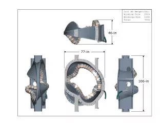
THE CMS MODULES FACTORY: A KEY POINT FOR THE SUCCESS OF THE COIL CONSTRUCTION! An area of 2200 m2 served by two 100 t cranes and a large lathe has been completely devoted to CMS module construction: Conductor in, Module out
Transportation of CMS modules (7.4 × 7.4 × 3.0 m3) was a hard task (at the limit of what can be transported on the road). Presently transportation of ITER toroidal coil 9 × 14.5 × 1.0 m3 seems possible. Of course it depends on where to where.
Conclusions • For an Al alloy based conductor the winding technology developed for CMS could mostly be used. Some improvements and need to check the feasibility of a 6 layer structure. • For a NbTi CIC conductor the winding methods depend on the coil lay out (double pancakes or rather a coil). For a pancake structure many external joints. Integration into a steel structure might be used for proving the needed longitudinal stiffness • Dimensions exceeding 7.2 m OD could pose serious transportation problems