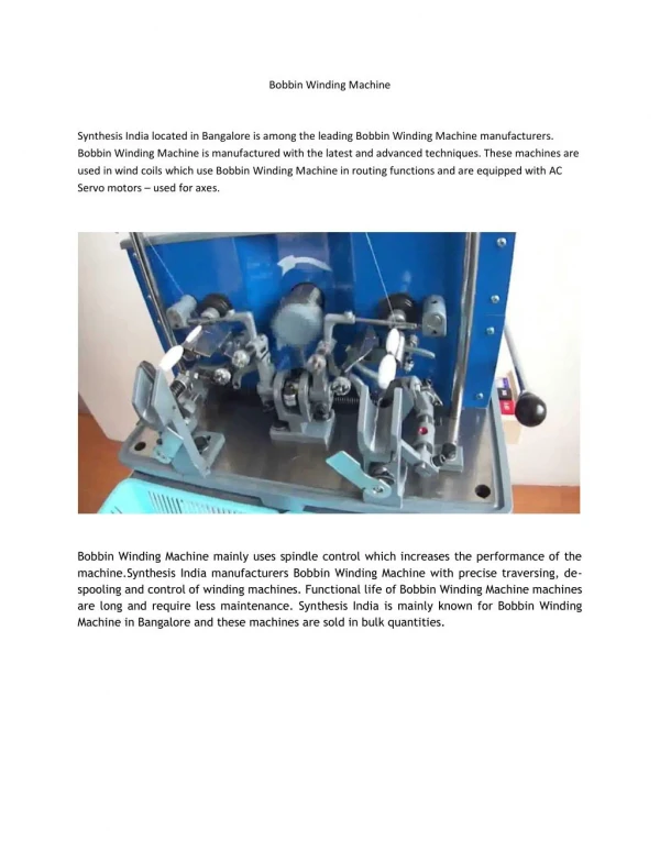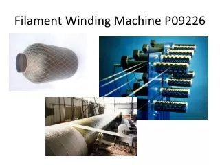
Winding technique
Winding technique. Just like oil filled transformers , there are varieties of windings in cast resin transformers too. Reliability & ease of manufacturing is aslo to be considered while deciding on any winding method. Major types in cast resin transformer windings methods are..

Winding technique
E N D
Presentation Transcript
Winding technique • Just like oil filled transformers , there are varieties of windings in cast resin transformers too. • Reliability & ease of manufacturing is aslo to be considered whiledecidingon any winding method. • Major types in cast resin transformer windings methods are.. • Low voltage winding • Foil winding using thin strip • Layer winding by using Rectangular wires. • High Voltage winding • Foil disc winding • Layer winding by using Round/Rectangular wire
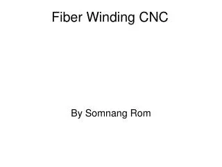
Winding technique • LV Foil winding: • It uses a single piece of thin strip as conductor. Width of the foil is equal to length of the winding. • This conductor strip (foil) wound along with a pre-impregnated interlayer insulation. During curing process foil and insulation are bonded together to form a rigid block. The LV coil becomes self supporting against forces. • Later the coil is impregnated with resin for environmental protection. • Eddy losses in the thin foil are very less compared to thick rectangular wires,so windings made with foil are cooler than other types. • Foil winding minimizes the axial forces during short circuit , since currents in the winding are adjusted to the ampere turns in the high voltage winding. • Issimple introduce coolingductwithoutdecreasing the mechanicalstregnt. • It is easy and quick to manufacture this type of winding.
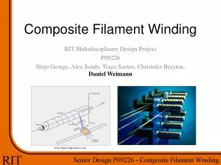
Winding technique Line terminal Terminalscomplitelywelded on allconducturheight Bushingsfixedtoclamps Al coolingduct
Winding technique • LV layer winding: • Multiple strands of rectangular wire is used in this method. • Conductor thickness is generally high to limit number of strands. So eddy & stray losses are high in this construction. • Transposition of conductors is mandatory to avoid the circulating currents in the windings. • Transposition is a tedious and sensitive process. If not done carefully inter-strand faults cause dielectric failures and hot spots in the winding. • Manufacturing the multistrand layer winding is complicated. • Winding is not balanced very well with the High voltage winding. Axial forces present during short circuit conditions. • It is not a self standing construction, requires support by cylinders. sometimes it is casted with moulds.
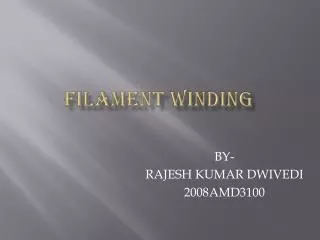
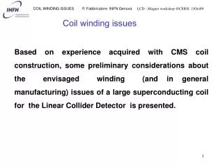
Winding technique Foil Winding Layer Winding
Winding technique • HV Foil disc winding: • Evendistribution of voltage along the height of the winding is important for High Voltage winding. • Foil disc winding is a winding technique which achives this requirement. • Thin foils of required width are wound with interlayer insulation between them. Each layer is a turn , so voltage stress isminimized. • Total turns are devided between many discs , so voltage gradient between discs is also low. • This can be made on automated machines , which gives accuracy & speed.
Winding technique • HV Foil disc winding:
Winding technique • HV wire winding: • Several winding methods are followed in wire winding • Multilayer winding , random winding , wirediscs winding etc. are some methods. • Generally round wire/rectangular wire is used for winding based on the rating. • Whatever the method followed , uniform voltage distribution is not possible in wire type windings. • Thisaffects the impulse withstand strength. • Voltage stress increases progressively towards the end of layer.
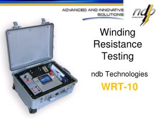
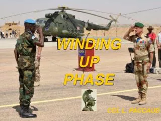
Winding technique Foil discs Wire discs Multilayer Random
Winding technique Foil disc winding Homogeneous distribution Wire disc winding Non Homogeneous distribution
Winding technique • What TMC Follows: • TMC follows Foil disc winding technique conisdering its uniform voltage distribution. • Example of 1600kVA transformer 36kV class. • Impulse level 170kV • Maximum voltage between discs , in case of impulse , 17kV with 14mm of resin. • Breakdown voltage of TMCRES resin 40kV/mm at 20°C
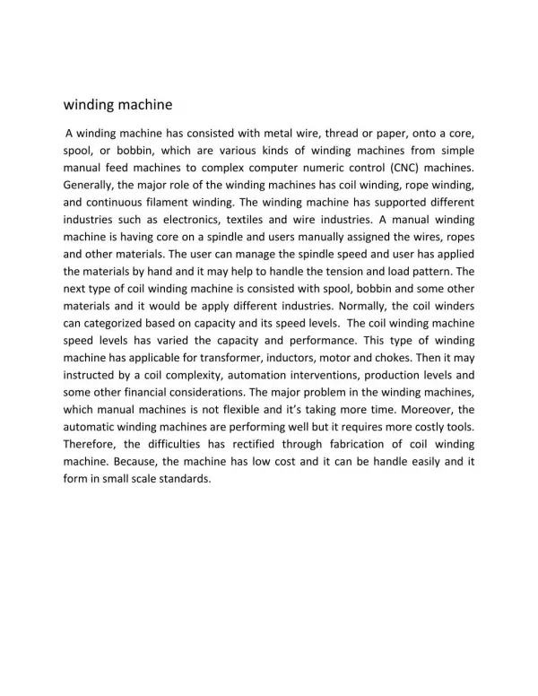
Filled Vs Unfilled system • Unfilled System: • Unfilled system , as the name suggests, does not use any type of fillers. Resin and Hardner are the main components. • Unfilled system is used where very low viscosity is a requirement . Ex: very small coils used in electrionics • Unfilled system can have smaller gaps in the coils , since the resin has low viscosity. • Casted block in the unfilled system ismanufacture with glassFibres. • Fibres needs to be completely impregnated for achieving the desirable dielectric & mechanical strength. • Fibres , if not impregnated properly , causes voids in the coil that results in dielectric failures. • Thissystem can be used with goodresults up 12 kVclass. When the voltage stress isnotvery high.
Filled Vs Unfilled system • Filled System: • Filled system means , resin & hardner are added with fillers like quartz/silica/aluminium hydroxide etc. • Fillers provide • Flame retardency, self extinguishing & arc resistance • Increases Thermal conductivity • Increases Thermal shock resistance • Reduce the shrinkage • Improve adhesion to the conductor • Brings the coefficient of thermalexpansion more close to conductor material. • Adding fillers increases the viscosity. But viscosity can be reduced by warming the resin mixture.
Filled Vs Unfilled system • What TMC Follows: • Filled system (or) Unfilled system is to be decided based on the product requirements. • TMC uses Filled resin system to fulfill the product requirements as mentioned above. • TMC products has C2-E2-F1 certificated. • TMC supplies transformers suitable for storage upto -50° C , which proves the strength of filled system. • Insulation material used in the filled system are self sufficient for dielectric strength. Impregantion by resin is not required.
Impregnated Vs Cast Windings • Impregnated windings : • Other names for this construction are Openwound/Openventilated windings/VPI/VPE • Does not require any moulds for winding. Flexibility in design. • The winding construction is simillar to disc windings of oil filled transformers. • Windings are immersed in resin and then cured. Resin coating on conductors is less than a milli meter. • provides clear view of the windings. Fault location is easy. • Heat dissipation directly from windings. • Strength aganist short circuits is poor. • Interspace between winding discs is air. Limited dielectric strength due to presence of air between discs.
Impregnated Vs Cast Windings • ....contd • Since windings are exposed to atmosphere around them , dust collection on surface of conductors is possible. • Mositure accumaltes on windings , if transformers are stored. • Transformers can not be switched on immedialtely after long shut downs. • Partial discharges possibility as air is the insulating medium. • Open wound transformers are not conisdered as maintenance free.
Impregnated Vs Cast Windings Filled Cast windings Unfilled Cast windings Impregnated windings
Impregnated Vs Cast Windings • Filled Cast windings : • Unique feature of cast resin transformer is conductors of HV winding are completely encapsulated in a cast resin block which has a smooth surface. • They require moulds to encapsule the windings. • Uses round/rectangular wire (or) Foil as the winding conductors. • Can use both Aluminium/Copper conductors. • Foil disc is most widely used option for HV winding. • Windings are made on mandrel ,moulds are fitted, Resin is filled and then cured. • Cast resin coils are non hygroscopic.Transformer can be switched on after long shut downs.
Impregnated Vs Cast Windings • ...contd • Cast Coils are perfectly mositure proof , dust proof & has very high reliability. • Very strong against short circuits as windings are encapsulated. • Heat dissipation surface area increases due to the encapsulation of the windings. • Low Partial discharges since gap between disc is filled with resin. • Cast resin transformers are practically maintenance free. • Cast winding conductors are not visible to naked eyes. • Repairability of windings is not an issue , if a transformer fails it is never repaired by an user.
Impregnated Vs Cast Windings • What TMC Follows: • TMC manufactures HV windings using mould • LV winding is made with AL/CU Foil. Mould are not used for casting. They are Impregnated. • Being low voltage , LV winding does not require casting • Insulation used in LV winding is pre impregnated with resins. During curing of LV winding insulation and conductor forms a rigid block. Later LV winding is impreganted with resin for environmental protection. • Such LV windings are suitable for installation under tropical or saline environmnets. • If customer requires cast LV winding , TMC supplies.
Copper Vs Aluminium • Both are used as conductors of electricity & long history of being used as winding conductors for transformes. • Copper is the preferred conductor during initial days of transformer manufacturing, due to it’s ready availability. • AL usage became prominent during world war2 due to non availability of Copper & improvement in metullargical processes of Aluminium. • We can achieve same performance parameters by using Allumninum (or) Copper windigs. • We can compare both conductors by • Electrical Properties • Thermal Properties • Mechanical Properties
Copper Vs Aluminium • Electrical Properties: • Copper has lesser resistivity. To achive same ohmic losses 1.5 -1.8 times higher cross section of Aluminium to be used. • Core cross section to be increased to offset the volume increase due to Aluminium conductor. • Specific weight of Aluminium is much lesser than copper. So weight of Aluminium is 50-55% of weight of copper. • Increase in core weight is compesated by reduction in conductor weight. • AL transforer will have almost equal weight as the copper transformer. • Volume is slightly higher than the copper transformer. (5-10%) • We can achieve same performance paramenters like noload/load losses, Impedance , temperature rise of windings using AL conductor.
Copper Vs Aluminium • Thermal Properties: • Melting point of Aluminium (665°C) is considerably lower than of Copper (1085°C). • The service tempearature of cast resin transformer is 155°C for class F and 180° C for class H transformers.So,Melting point is not of importance. • Thermal conductivity of Aluminium is lower than copper.But while calculating thermal gradients between winding and ambient air whole coil is take as a block. So heat dissipation does not depend solely on the Thermal conductivity. • Surface area of Aluminium is higher than Copper for same losses. Moreover, specific heat of Aluminium is more than copper. • Higher surface area and higher specific heat makes Aluminium coils cooler than copper coils for same losses.
Copper Vs Aluminium • ....contd • This is an advantage for longer life of insulation and also during short time overloads. • Incase of resin encapsulated transformers , it is very important that the co-efficient of thermal expansion of conductor and resin block needs to be close. If they differ too much, cracks develop during varying load cycles. • Aluminium co-efficient is close to the resin mixture, which makes this conductor more suitable for cast coils.
Copper Vs Aluminium • Mechanical Properties : • Conductors in the transformers are stressed during the fault conditions. • The forces generated during faults are expressed as compression , tesion and bending between coil supports. • Breaking strength of Aluminium is lesser than the copper. It is compensated by the higher cross section of Aluminium used for same current. • Further High voltage windings are encapsulated in the resin block. Hence , the mechanical strength is provided by the resin. • For Low voltage Foil windings, using preimpregnated insulation and curing it subsequently makes the coil as a rigid block to withstand forces.
Copper Vs Aluminium • .... contd • Aluminiumwindings can be designed to have same mechanical integrity as of copper windings. • Other Considerations: • Larger surface area of the Aluminum windings improves the series capacitance , which is favourable for Impulse voltage withstand. • Improvements in jointing techniques has made Aluminum to easily and reliably join with copper (or ) other Aluminium conductors. • Price of Copper is very much volatile and ~ 3,5 times of the price of Aluminium.
Copper Vs Aluminium • What TMC Follows: • It can be concluded that medium power transformers upto 20 MVA can be manufactured with Aluminium windings without any difficulty. • Aluminium windings are default for TMC. • Aluminium winding transformers are cheaper by 50 - 60 % for same performance. • Copper winding transformers will be supplied by TMC , if customer requires them.