Composite Filament Winding Machine
Composite Filament Winding Machine. P09226 Dept of Mech Eng (Sponsor) Dr. Alan Nye (Faculty Advisor). Background What: We aim to produce a low cost, automated filament winding machine through which RIT students can develop and actively learn about composite tube manufacturing. Why:

Composite Filament Winding Machine
E N D
Presentation Transcript
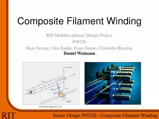
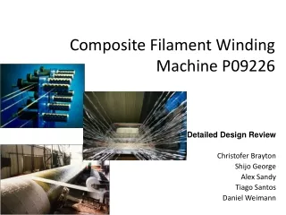
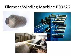
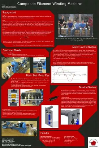
Composite Filament Winding Machine P09226 Dept of Mech Eng (Sponsor) Dr. Alan Nye (Faculty Advisor) • Background • What: • We aim to produce a low cost, automated filament winding machine through which RIT students can develop and actively learn about composite tube manufacturing. • Why: • The Mechanical Engineering Department lacks the ability to develop composite tubing by its own accord. Using this project as a stepping stone, further learning can go into designing and producing this tubing. • Student-run organizations, such as Formula SAE and Baja SAE, have great need for composite tubes because of their high strength to weight ratio, but are turned away from the high cost of labor and production. • How: • Donated from Dr. Hany Ghoniem, the team worked with a Craftsman Mk. 1 6-inch lathe because its basic functions are the foundation for simple filament winding. The rotating headstock controls the mandrel while the rack and geared tool carriage guide the fiber as it’s laid. The fiber orientation angle that determines the characteristics of the finish part can be determined by the following formula: Alexander Sandy (ME), Christofer Brayton (EE), Tiago Santos (ME), Daniel Weimann (ME), Shijo George (ME) where, θ is the fiber orientation angle; Nm is the rotational speed of the mandrel (lathe headstock); and Vc is the translation speed of the feed eye (lathe carriage) More information can be found at https://edge.rit.edu/content/P09226/public/Home Customer Needs Robust, Mobile Design Simple assembly/disassembly/clean-up Well documented foundation for future learning and development • Motor Control System • An ATMAGA128 Microcontroller stores position and velocity tables that map out the direction and number of steps for the stepper motors that drive the mandrel and feed eye • The mandrel spins up to speed and the maintains that speed until the end of the process • The feed eye proceeds back and forth across the mandrel; pausing at each end to ensure a full 180° wrap around before reversing direction • The graph maps out the velocity profiles of both the mandrel and feed eye (steps vs. msec) and the position profile of the feed eye • Future Iterations • Active feedback to respond to fiber breaks or other emergency stops automatically • Speed and position control to wrap mandrels of varying cross sections and those that contain bends and joints • Resin Bath/Feed Eye • The Fiber Dip bath bends fiber in and out of a pool of resin for impregnation • Rollers are used to reduce fiber abrasion and spread out resin onto fiber as it passes through • Squeeze rollers located at the end of the bath remove excess resin prior to being laid up onto mandrel • The feed eye is fixed onto the exit point of the resin bath and is made of ceramic to avoid unnecessary fiber abrasion • Tension System • Rubber bushings create friction to limit spool from gaining momentum as it loses inertia (using up fiber) and provide resistance to pulling fiber • The bushings can be tightened or loosened corresponding to amount of tension desired • Future Iterations • A new tension system was designed for more accurate and precise control of tension applied to the fiber. Feeding the fiber through a system of pulleys, the spring loaded center pulley rises or lowers corresponding to the amount of tension applied. The tension is reflected through a flag that concurrently allows a certain amount of light from an LED to a light sensor. The light sensor communicates to a DC motor to run faster, slower, or not at all or adjust to the desired tension. • Future Iterations • Different materials for the running rollers and squeegee rollers can be used to determine varying effectiveness • Using a heating plate set to 50°C will be able to keep resin at lower viscosity to maintain better, consistent impregnation during winding process Results Machine Capabilities: Minimum Wrap Angle: 70° (@ 20 RPM) Maximum WrapAngle: 85° (@ 50 RPM) Fiber Volume Fraction: TBD Outer Diameter: 1’’ or 2’’ Max Length: 12’ Part Specifications: Wrap Angles: 70° – 85° Fiber Volume Fraction: TBD Outer Diameter: 1’’ or 2’’ Thickness: 1/16’’ Max Length: 6’ • SPECIAL THANKS TO: • DR. DAVID ORLICKI • MR. CARL LUNDGREN • DR. HANY GHONEIM • MECHANICAL ENGINEERING DEPT • ROB KRAYNIK AND ME MACHINE SHOP PERSONNEL