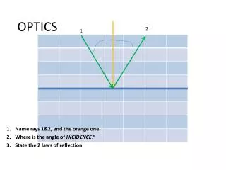
Optics
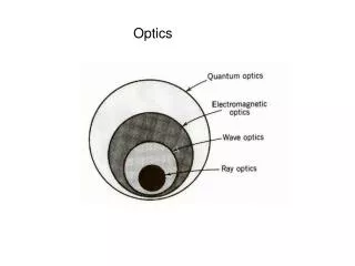
Chapter 11. Optics. Shanghai Normal University Department of Physics. Development of Optics. Geometrical optics. Wave optics. Quantum optics. Wave optics :. Interference? Diffraction? Polarization?. 本章目录. Catalog of Chapter 11. 11-0 Teaching Basic requirements.


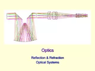
Optics
E N D
Presentation Transcript
Chapter 11 Optics Shanghai Normal University Department of Physics
Development of Optics Geometrical optics Wave optics Quantum optics Wave optics: Interference? Diffraction? Polarization?
本章目录 Catalog of Chapter 11 11-0 Teaching Basic requirements 11-1 Coherent Light 11-2 Young’s Double – slit Interference, Lloyd Mirror 11-3 Optical Path, Film Interference 11-4 Wedge, Newton’s Ring 11-5 Michelson Interferometer 11-6 The Diffraction of Light 11–7 Single – slit Diffraction
Catalog of Chapter 11 11- 8 Hole Diffraction, the Resolution Capability of Optical Instruments 11- 9 Diffraction Grating 11-10 The Polarization of Light, Malus Law 11-11 The Polarization of Reflected Light and Refracted Light 11-12 The Birefringence *11-13 The Liquid Crystal Display *11-14 Geometrical Optics
11-0 Teaching Basic requirements Interference of Light 1. Understandthe interference condition and the method of getting coherent light 2. Master concept of optical path as well as relationship of the optical path difference and the phase difference, and understand under what circumstances the reflected light has phase jump.
11-0 Teaching Basic requirements 3. Analyze position of Young’s double-slit interference fringes and film thickness interference fringe . 4. Understand principle of Michelson interferometer .
11-0 Teaching Basic requirements The Diffraction of Light 1.Understand the Huygens-Fresnel principle and its qualitative interpretation of diffraction phenomenon of light. 2. Understand using zone method to analyze distribution of single-slit Fraunhofer diffraction fringes, and analyze the effect of the slit width and wavelength on distribution of diffraction fringes.
11-0 Teaching Basic requirements 3. Understand grating diffraction formula, determine the position of grating diffraction line, analyze the effect of grating constant and the wavelength on the grating diffraction spectrum. 4.Understand the effect of the diffraction of optical instrument resolution. . 5. Understand the x-ray diffraction phenomenon and the physical meaning of Prague formula.
11-0 Teaching Basic requirements The Polarization of Light 1.Understand difference of Nature light and Polarized light. 2. Understand Brewster law and Marius's law. 4. Understand the method of getting and testing linearly polarized light. 3. Understand birefringence of light.
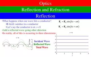
Plane Electromagnetic Wave Equation 11-1 Coherent Light I. Light wave is the electromagnetic wave (traverse wave) Light vector:the component who can produce the vision of eyes and the sensitization on the photographic plate is the vector E called light vector. E oscillation is called light oscillation.
The speed of light in vacuum (Refractive index of the medium) 11-1 Coherent Light The speed of light in vacuumc and the speed of light in transparent mediumu are:
11-1 Coherent Light Light source: object of emitting light. Ordinary light emitting mechanism is the spontaneous radiation of the atomic. (Atoms and molecules in the absorption of energy are in an unstable excited state, even in the absence of any external forces, they would spontaneously return to low excited state and ground state, at the same time sending out light.)
11-1 Coherent Light The light source and the mechanical wave source detected difference: mechanical wave source is often a vibrating object, while the light source is thousands on thousands of atoms which randomly emits light as one falls.
11-1 Coherent Light According to the light excited method, the light source can be divided into: Heat light source: exciting light utilizing heat energy (Incandescent lamp) Cold light source:exciting light utilizing chemical energy (such as phosphor), power (such as fluorescent lamps) or light energy (such as fluorescent, phosphorescent) Range of visual light
11-1 Coherent Light The monochromatic light The monochromatic light: a sine (cosine) light wave with a constant frequency and an infinite length Although yellow light emitting from a Sodium lamp has a wavelength of 5893 A, it is not monochromatic strictly. 0
11-1 Coherent Light Polychromatic light:lightcomposited by various frequency light ( such as white light ). Polychromatic light can produce dispersion phenomenon through the three prism.
Excited state Ground state Atomic energy level transition and luminescence 11-1 Coherent Light II.Coherent Light 1.light emitting mechanism of the normal light source:the spontaneous radiation of atoms (molecules).
1 P 2 11-1 Coherent Light Light-emitting characteristics of normal light source:is intermittent, each light to form a short wavAtomic emission e train, the atoms of each luminous independently of each other, each wave train irrelevant.
Sodium lamp A Two beams of light are Incoherent ! Sodium lamp B 11-1 Coherent Light Coherent Light:If light vectors of two light beams satisfy the interference condition, they are the coherent light. The relative light sources are called the coherent light source.
Sodium lamp A Two beams of light are Incoherent ! Sodium lamp B 11-1 Coherent Light Two independent light sources may not be a pair of coherent light source. Reason: Atomic emission is random as well as intermittent, so vibration directions of two columns of light can not be the same, and phase difference may not be constant.
11-1 Coherent Light The basic idea of realizing optical interferometer: The light from each light were decomposed into two sub-light columns, and then let the two sub-light columns in the same area and produce interference. 。
11-1 Coherent Light Two kinds of specific practices: (1)Method of dividing wave front (Fig. a),e.g. , Young’s two slit interference. (2)Amplitude segmentation(Fig. b)
(a) Method of dividing wave front (b) method of dividing amplitude The light through the two slits is deco posited two sub-light columns. A wave train is divided into two coherent wave trains by reflected of the two interfaces of film. 11-1 Coherent Light
Wave front segmentation method Oscillation amplitude segmentation method Source * 11-1 Coherent Light 2 Production of coherent light
p Wave path difference 11-2 Young’s Double – slit Interference, Lloyd Mirror I. Experiment of Young’s Double – slit Interference experimental device
实 验 装 置 p Strengthen Weaken 11-2 Young’s Double – slit Interference, Lloyd Mirror
bright fringes Dark fringes 11-2 Young’s Double – slit Interference, Lloyd Mirror p
11-2 Young’s Double – slit Interference, Lloyd Mirror Distance between the centers of adjacent bright fringes bright fringes dark fringes Distribution of the bright and dark fringes If white light is used, color fringes appear. The bright and dark fringes distribute in eaual distance.
(1) are constant, if changes, thenhow will changes? 11-2 Young’s Double – slit Interference, Lloyd Mirror Distance Light intensity of each fringe is equal.
(2) Keep constant, what relationship between and ? 11-2 Young’s Double – slit Interference, Lloyd Mirror
11-2 杨氏双缝干涉实验 劳埃德镜 11-2 Young’s Double – slit Interference, Lloyd Mirror • Example 1 In Young’s double – slit interference experiment, a Sodium light with the wavelength =589.3 nm is used as the light source. The distance d’=800 nm between the screen to the double-slit. The question: • When the distance between two slits is 1 mm, how much is the distance between the centers of adjacent bright fringes? • Assuming the distance between two slits is 10 mm, how much is the distance between the centers of adjacent bright fringes?
11-2 Young’s Double – slit Interference, Lloyd Mirror Known =589.3 nm d`=800 nm Ask (1)d=1 mm时 (2)d=10 mm时 (1) As d=1 mm, Solution (2) If d=10 mm, then
11-2 Young’s Double – slit Interference, Lloyd Mirror Example 2: Two slits with the gap of 0.2 mm are irradiated by the monochromatic light, and the distance between double-slit and the screen is 1 m. Question: (1)The distance is 7.5 mm from the first order bright fringe to the fourth order bright fringe in the same side, what the wavelength of the monochromatic light is? (2)If the wavelength of the incident light is 600 nm, how much the distance is from the center of the central bright fringe to the center of the closest adjacent dark fringe?
11-2 Young’s Double – slit Interference, Lloyd Mirror Known Ask (1) (2) Solution (1) (2)
11-2 Young’s Double – slit Interference, Lloyd Mirror IIThe effect of the slit width to the fringes, space coherence In the experiment, meanwhile the slit width is increasing gradually, the fringes on the screen is going to be faintness gradually, and disappear finally. space coherence
L Half wave expense: when light eradiate from the media with higher light velocity into one with lower light velocity, the phase of reflected light transits comparing with that of the incidence light. 11-2 Young’s Double – slit Interference, Lloyd Mirror III Lloyd Mirror P M
n n If < , call medium 1 optically thinner medium and medium 2 optically denser medium 1 2 incidence light Reflected light n 1 Refractive light n 2 11-2 Young’s Double – slit Interference, Lloyd Mirror The half wave expense will occur when light eradicates from the optically thinner medium to optically denser medium and is reflected by the interface. The refraction of light is without half wave expense.
C A 2 B 1 11-2 Young’s Double – slit Interference, Lloyd Mirror Example 3 as shown in the figure, there is an electromagnetic wave receiver on the C position where is with the height h=0.5 m above the lake surface. As a radio star is rising gradually from the ground level on the left side, the receiver measured brokenly a serious of maximum value. It is known that the wavelength of the electromagnetic wave emitted by the radio star is 20.0 cm, what the azimuth angle is between the radio star and the ground level as the first maximum value is measured?
C A 2 B 1 The maximum value is 11-2 Young’s Double – slit Interference, Lloyd Mirror Solution:calculate wave path-difference
C Note A 2 B 1 It is necessary here to explain that is all reasonable to take as calculating the additional wave path-difference. To take does not affect the essential of the problem but choosing the value of k. 11-2 Young’s Double – slit Interference, Lloyd Mirror
Light speed in vacuum Light speed in the medium Wavelength in vacuum Wavelength in the medium Refractive index of medium 11-2 Young’s Double – slit Interference, Lloyd Mirror IVOptical path, optical path-difference
* P * 11-2 Young’s Double – slit Interference, Lloyd Mirror
Wavelength in the medium * P * • wave path-difference • phase difference 11-2 Young’s Double – slit Interference, Lloyd Mirror
* P * 11-2 Young’s Double – slit Interference, Lloyd Mirror (1) opticalpath The product of the refractive index of the medium and the geometry of the light path = The physical meaning:The optical path is the distance in vacuum which is equally calculated from the geometric distance of light in the medium according to the phase difference .
* optical path-difference P Phase difference * 11-2 Young’s Double – slit Interference, Lloyd Mirror (2) optical path-difference
constructive interference • destructive interference 11-2 Young’s Double – slit Interference, Lloyd Mirror
r P 1 S x 1 r φ 2 d O φ D S ~ ~ 2 x sin d d D 11-2 Young’s Double – slit Interference, Lloyd Mirror Young’s Double – slit experiment:when light obliquely incidents to double slits, optical path is: Bright fringes Dark fringes
n1 t1 r P 1 x S 1 r φ O` 2 d n2 t2 O φ S 2 d` 11-2 Young’s Double – slit Interference, Lloyd Mirror When the optical paths 1,2 are respectively inserted into two transparent medium sheets with the refractive index of n1 and n2, thickness of t1and t2, the optical path-difference will be:
A B Focal plane A B 11-2 Young’s Double – slit Interference, Lloyd Mirror (3) The lens does not introduce the additional optical path difference
Optical path= Refractive index Geometrical distance + Optical path-difference n r n r = 2 2 1 1 = 11-3 Optical path thin film interference n r = Bright fringes = Dark fringes