Download
1 / 14
140 likes | 301 Vues
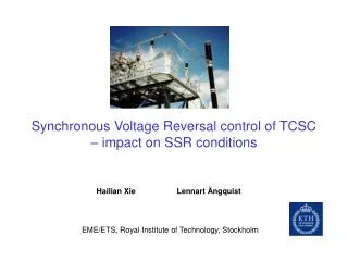
Synchronous Voltage Reversal control of TCSC – impact on SSR conditions. Hailian Xie Lennart Ängquist. EME/ETS, Royal Institute of Technology, Stockholm. Series compensation. capacitor bank inserted in series with transmission line

E N D
Synchronous Voltage Reversal control of TCSC– impact on SSR conditions Hailian Xie Lennart Ängquist EME/ETS, Royal Institute of Technology, Stockholm
Series compensation • capacitor bank inserted in series with transmission line • aims to increase the power transfer capacity of high-voltage transmission line • fixed capacitor bank may cause a Torsional Interaction Sub-Synchronous Resonance (TI-SSR) problem with thermal power generators • Thyristor Controlled Series Capacitor (TCSC) may solve this problem EME/ETS, Royal Institute of Technology, Stockholm
TCSC main circuit and generic waveforms Line current Valve current Capacitor voltage Apparent reactance EME/ETS, Royal Institute of Technology, Stockholm
About this paper • describes the laboratory setup of a TCSC model with the SVR (Synchronous Voltage Reversal) control scheme • presents the result from an investigation concerning the impact of the SVR controlled TCSC on SSR in the real-time simulator EME/ETS, Royal Institute of Technology, Stockholm
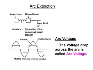
TCSC inductance Thyristor valve Source 1 impedance Line Fixed Impedance capacitor Infinite bus u2 u1 TCSC capacitor Diagram of the real-time simulator EME/ETS, Royal Institute of Technology, Stockholm
SVR idea: control capacitor voltage zero-crossing instant SVR Control scheme EME/ETS, Royal Institute of Technology, Stockholm
SVR boost control system overview TCSC capacitor TCSC inductance pulses SVR trig pulse generation kBref+ kBm _ Boost controller Thyristor valve PLL uc(measured) -XC0 Re Im Apparent Z evaluation Phasor estimation il (measured) EME/ETS, Royal Institute of Technology, Stockholm
Method to analyze the system damping In DSP In Matlab u1 Generate system voltage Control modulation Kel Del Re(ΔTel) Im(ΔTel) Calculate the spring constant and damping coefficient iL Calculate the electrical torque Tel LP filter EME/ETS, Royal Institute of Technology, Stockholm
Electrical damping curve (1) system with fixed series compensation EME/ETS, Royal Institute of Technology, Stockholm
Electrical damping curve (2) system with SVR controlled TCSC EME/ETS, Royal Institute of Technology, Stockholm
Electrical damping curve (3) Comparison between SVR and control EME/ETS, Royal Institute of Technology, Stockholm
Electrical damping curve (4) SVR control with different parameters EME/ETS, Royal Institute of Technology, Stockholm
Conclusions • at low boost factor, SVR controlled TCSC can provide much better damping than conventional control scheme that controls the firing angle directly • the damping characteristic of SVR controlled TCSC with respect to SSR is almost independent of the boost factor • the tuning of the boost controller and PLL makes no critical difference on the TCSC SSR behavior EME/ETS, Royal Institute of Technology, Stockholm
Thank you! EME/ETS, Royal Institute of Technology, Stockholm