Download
1 / 34
340 likes | 490 Vues
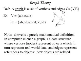
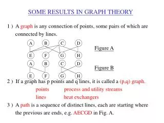
SOME RESULTS IN GRAPH THEORY. 1 ) A graph is any connection of points, some pairs of which are connected by lines. 2 ) If a graph has p points and q lines, it is called a (p,q) graph. points process and utility streams

E N D
SOME RESULTS IN GRAPH THEORY 1 ) A graph is any connectionof points, some pairs of which are connected by lines. 2 ) If a graph has p points and q lines, it is called a (p,q) graph. points process and utility streams lines heat exchangers 3 ) A path is a sequence of distinct lines, each are starting where the previous are ends, e.g. AECGD in Fig. A. A B C D Figure A Figure B E F G H A B C D E F G H
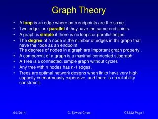
SOME RESULTS IN GRAPH THEORY 4 ) A graph is connected if any two points can be joined by a path, e. g. Fig. A 5 ) Points which are connected to some fired point by paths are said to form a component, e. g. Fig A has one component. Fig B has two components. 6 ) A cycle is a path which begins and ends at the same point, e. g. CGDHC in Fig. A. 7 ) The maximum number of independent cycles is called the cycle rank of the graph. 8 ) The cycle rank of a (p,q) graph with k components is q - p + k
A Result Based on Graph Theory U = N+L-S Where, N = the total number of process and utility streams L = the number of independent loops S = the number of separate component in a network U = the number of heat exchanger services
U = N+L-S 30 70 90 ST H1 H2 U = N-1 = 5 U = N-2 = 4 U = N+1-1 = N = 6 30 10 60 40 50 C1 C2 CW 40 100 50 30 70 90 ST H1 H2 30 70 40 50 C1 C2 CW 40 100 50 30 70 90 ST H1 H2 X 60-X 30-X 10+X 40 50 C1 C2 CW 40 100 50
CAPITAL TARGET Umin = N - 1 where, Umin = the minimum number of services N = the total number of process and utility streams Note, U = N + L - S
§ PINCH DESIGN METHOD RULE1: THE “TICK-OFF” HEURISTIC UMIN = N-1 - THEEQUATIONISSATISFIEDIFEVERYMATCH BRINGS ONE STREAM TO ITS TARGET TEMPERATURE OR EXHAUSTS A UTILITY. - FEASIBILITY CONSTRAINTS : ENERGY BALANCE TMIN
Example 1 Stream No TS TF CP Heat Load and Type (F)(F)104BTU/hr FQ BTU/hr (1) Cold 200 400 1.6 320.0 (2) Cold 100 430 1.6 528.0 (3) Hot 590 400 2.376 451.4 (4) Cold 300 400 4.128 412.8 (5) Hot 471 200 1.577 427.4 (6) Cold 150 280 2.624 341.1 (7) Hot 533 150 1.32 505.6 Tmin = 20F Qhmin = 217.5 104 BTU/hr Qcmin = 0
Hot streams CP Q 2.376 451.4 1.557 427.4 1.32 1.6 320.0 1.6 528.0 4.128 412.8 2.624 590 400 471 419 200 533 150 400 200 430 100 400 300 280 150 3 5 505.6 7 1 416 2 505.6 4 341.1 6 341.1 Cold streams
CP Q 2.376 451.4 1.557 1.6 320.0 1.6 22.4 4.128 590 574 400 471 419 400 200 430 416 400 300 3 86.3 5 254 1 86.3 2 412.8 4 412.8
CP Q 2.376 38.6 1.6 233.7 1.6 22.4 590 583 574 400 264 254 430 416 3 1 H 217.5 16.2 2 22.4
CP Q 2.376 451.4 1.557 427.4 1.32 1.6 320.0 1.6 528.0 4.128 412.8 2.624 590 400 471 200 533 150 400 200 430 100 400 300 280 150 3 5 505.6 7 H 1 16.2 217.5 86.3 2 22.4 505.6 4 412.8 341.1 6 341.1
§ PINCH DESIGN METHOD RULE 2: DECOMPOSITION - THE HEN PROBLEM IS DIVIDED AT THE PINCH INTO SEPARATE DESIGN TASKS. - THE DESIGN IS STARTED AT THE PINCH AND DEVELOPED MOVING AWAY FROM THE PINCH.
DATAFOREXAMPLEII Temperature Heat Capacity Supply Target Flowrates Heat load Process Stream TS TT CP Q no. Type F F 104 BTU/h/F 104 BTU/h 1 Cold 120 235 2.0 230.0 2 Hot 260 160 3.0 300.0 3 Cold 180 240 4.0 240.0 4 Hot 250 130 1.5 180.0 Tmin = 10 F QHmin = 50 104 BTU/h QCmin = 60 104 BTU/h
PINCH 260 190 190 160 2 250 190 190 130 4 240 180 180 120 1 240 180 3 C = 60 Btu/h H = 50 Btu/h Umin = 4 Umin = 3 PINCH DECOMPOSITION DEFINES THE SEPARATE DESIGN TASKS
BELOW THE PINCH CP Q 3 90 1.5 90 2 120 190 160 2 3 190 170 130 4 4 G 60 190 135 120 3 4 1 90 30 ABOVE THE PINCH CP Q 3 210 1.5 90 2 220 4 240 260 190 2 1 250 190 4 2 235 225 180 H 2 1 20 90 240 -32 180 H 1 3 30 210
Cp Q 3 300 1.5 180 2 230 4 240 260 160 1 3 2 250 130 2 4 C 4 60 235 120 H 2 3 4 1 20 90 90 30 240 180 H 1 3 30 210 THE COMPLETE MINIMUM UTILITY NETWORK
PINCH MATCH Pinch A Pinch Match Pinch 2 1 Exchanger 2 is not a pinch match Pinch 3 2 1 Exchanger 3 is not a pinch match
FEASIBILITY CRITERIA AT THE PINCH Rule 1: Check the number of process streams and branches at the pinch point Above the Pinch : PINCH PINCH 90 90 90 80 80 90 90 90 80 80 1 1 2 2 3 3 (80+T1) 4 4 (80+T2) Q1 5 5 Q2 Tmin = 10C Tmin = 10C
FEASIBILITY CRITERIA AT THE PINCH Rule 1: Check the number of process streams and branches at the pinch point Below the Pinch : 90 90 90 80 80 (90-T1) 90 90 80 80 80 1 1 (90-T2) 2 2 3 3 4 4 Q1 5 5 Q2 PINCH PINCH Tmin = 10C
FEASIBILITY CRITERIA AT THE PINCH Rule 2: Ensure the CP inequality for individual matches are satisfied at the pinch point. Above the Pinch : Below the Pinch : CPH1 CPC3 1 1 CPH2 CPC4 2 2 3 3 Q2 4 4 PINCH Q1 PINCH 1 T 2 T Tmin Tmin 3 4 Q Q Q2 Q1 CPC CPH CPC CPH
Stream data at the pinch NH NC? Yes No CPH CPC for every pinch match Split a cold stream No Yes Split a stream ( usually hot) Place pinch matches Figure 8.7-7 Design procedure above the pinch. (From B. Linnhoff et al., 1982.)
Stream data at the pinch NH NC? Yes No CPH CPC for every pinch match Split a cold stream No Yes Split a stream ( usually hot) Place pinch matches Figure 8.7-7 Design procedure below the pinch. (From B. Linnhoff et al., 1982.)
CRITERION #3 THE CP DIFFERENCE ABOVETHE PINCH, INDIVIDUAL CP DIFFERENCE = CPC - CPH OVERALL CP DIFFERENCE = BELOWTHE PINCH, INDIVIDUAL CP DIFFERENCE = CPH - CPC OVERALL CP DIFFERENCE = THESUM OF THE INDIVIDUAL CP DIFFERENCES OF ALL PINCH MATCHES MUST ALWAYS BE BOUNDED BY THE OVERALL CP DIFFERENCE.
PINCH CP 4 2 5 3 Overall CP Difference = 8 - 6 = 2 Total Exchanger CP Difference = 1 + 1 = 2 O.K.
PINCH CP 4 2 5 3 1 Overall CP Difference = 9 - 6 = 3 Total Exchanger CP Difference = 1 + 1 = 2 O.K.
PINCH CP 3 2 8 1 Overall CP Difference = 9 - 5 = 4 Total Exchanger CP Difference = 8 - 2 = 6 Criterion violated !
Cp Q 3 300 1.5 180 2 230 4 240 260 190 160 1 3 2 250 190 170 130 2 4 C 4 60 235 225 180 135 120 H 2 3 4 1 20 90 90 30 240 232.5 180 H 1 3 30 210 Heat Load Loops heat loads can be shifted around the loop from one unit to another
4 H 2 3 H 2 4 1 H C 1 3 C Heat Load Loops heat loads can be shifted around the loop from one unit to another
260 190 160 1 3 2 250 170 130 2 C 4 60 235 225 165 120 H 2 3 1 20 120 90 240 232.5 180 H 1 3 30 210 Heat Load Path heat loads can be shifted along the path
4 H 2 3 H 2 1 H C 1 3 C Heat Load Path heat loads can be shifted along the path
Cp Q 3 300 1.5 180 2 230 4 240 260 190 160 1 3 2 2 250 175 130 C 4 60+X 235 221.25 165 120 2 3 H 1 20+X 112.5 90 240 232.5 180 H 1 3 30 210 X=7.5
Two ways to break the loop If: L1>L4 L2>L3 then: X=L4 or X= -L3 1 1 2 2 3 4 (a) 3 L2 + X L4 - X 4 L3 + X L1 - X 1 2 3 2 1 4 3 4
heater/cooler can be included in a loop 1 3 4 2 (b) H1 - X 3 H L3 + X 4 H L4 - X H2 + X 1 H 3 4 3 4 Figure 2.28 - Complex loops and paths
Match 1 is not in the path 1 2 3 2 1 4 C (c) C + X 3 L3 + X L4 - X 4 H L2 - X H + X H 1 2 4 2 3 4 3 C Figure 2.28 - Complex loops and paths