Download
1 / 22
220 likes | 350 Vues
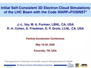
Initial Self-Consistent 3D Electron-Cloud Simulations of the LHC Beam with the Code WARP+POSINST*. J.-L. Vay, M. A. Furman, LBNL, CA, USA R. H. Cohen, A. Friedman, D. P. Grote, LLNL, CA, USA. Particle Accelerator Conference May 16-20, 2005 Knoxville, TN, USA.

E N D
Initial Self-Consistent 3D Electron-Cloud Simulations of the LHC Beam with the Code WARP+POSINST* J.-L. Vay, M. A. Furman, LBNL, CA, USA R. H. Cohen, A. Friedman, D. P. Grote, LLNL, CA, USA Particle Accelerator Conference May 16-20, 2005 Knoxville, TN, USA • *Work supported by the U.S. DOE under LLNL and LBNL contracts W-7405-Eng-48 and DE-AC03-76F00098.
ABSTRACT We present initial results for the self-consistent beam-cloud dynamics simulations for a sample LHC beam, using a newly developed set of modeling capability based on a merge [1] of the three-dimensional parallel Particle-In-Cell (PIC) accelerator code WARP [2] and the electron-cloud code POSINST [3]. Although the storage ring model we use as a test bed to contain the beam is much simpler and shorter than the LHC, its lattice elements are realistically modeled, as is the beam and the electron cloud dynamics. The simulated mechanisms for generation and absorption of the electrons at the walls are based on previously validated models available in POSINST [3, 4].
ECE simulations usually based on two extreme “first-order” simulation models, 2-D or 3-D • dynamical evolution of e-cloud as a set of macroparticles under action of successive bunches; beam=prescribed f(x,t); • study of e-cloud intensity and space-time evolution, • dynamical evolution of beam(s) as a set of macroparticles under action of e-clouds; electrons=prescribed f(x,t); • assessment of emittance growth and beam instabilities.
or B. is sufficient in many cases but 3-D self-consistency is sometimes necessary • For example: • the longitudinal flow of electrons, especially across lattice elements, particularly for long-pulse beams; • the interaction of the beam and electron cloud with residual and desorbed gas (ionization, charge exchange, secondary ionization, beam-particle-wall collisions, etc). • However, 3-D self-consistency is very demanding: long systems, many macroparticles, complex geometries,… • requires advanced numerical techniques & supercomputers. • Examples of codes that include self-consistent features to a lesser or greater extent are given in Ref.[6].
Integrated R&D program of dedicated diagnostics, measurements and simulations of ECEs [7] • A collaboration between LBNL, LLNL, UC Berkeley and Tech-X Corp. • Centered around • the High Current Experiment (HCX) at LBNL [8] (initially conceived as prototype of heavy-ion fusion driver), • the WARP-POSINST simulation package. Focus of Current Gas/Electron Experiments 1 MeV, 0.18 A, t ≈ 5 s, 6x10¹² K+/pulse INJECTOR MATCHING SECTION ELECTROSTATIC QUADRUPOLES MAGNETIC QUADRUPOLES Additional Experiments: Fill-Factor Measurements, Head-Tail Correction, Wave Experiments
Key: operational; partially implemented (5/6/05) Development of self-consistent modeling tools of beam with e-cloud & gas effects follows a “roadmap”. fb,wall WARP ion PIC, I/O, field solve fbeam, F, geom. gas module Reflected ions emission from walls ambient fb,wall nb, vb gas transport ions fb,wall volumetric (ionization) electron source wall electron source charge exch. ioniz. F electron dynamics (full orbit; interpolated drift) sinks ne
We have merged WARP and POSINST. framework & user interface WARP Python field calculator image forces ion mover electron source modules xi, vi diagnostics kicks from beam electron mover lattice description POSINST
WARP has many well-tested features … • Geometry: 3D, (x,y), or (r,z) • Field solvers: FFT, capacity matrix, multigrid • Boundaries: “cut-cell” --- no restriction to “Legos” • Bends: “warped” coordinates; no “reference orbit” • Lattice description: general; takes MAD input • solenoids, dipoles, quads, sextupoles, … • arbitrary fields, acceleration • Beam injection: Child-Langmuir, and other models • Diagnostics: Extensive snapshots and histories • Parallel: MPI • Python and Fortran: “steerable,” input decks are programs • a GUI is also available
… and new features advancing the state of the art ... R (m) Z (m) 1 . 0 Low res. Medium res. High res. Low res. + AMR 0 . 8 mm.mrad) 0 . 6 p ( 0 . 4 NRMS e 4 0 . 2 0 . 0 0 . 1 0 . 2 0 . 3 0 . 4 Z ( m ) • Adaptive mesh refinement (3-D , x-y, and r-z) • - LHC 3-D simulation: Cell count reduced 20,000x • New electron mover that allows large time steps • E-cloud and gas models • Prototype Vlasov solver (for halo) Beam coming off source x 11 speedup
Problem: Electron gyro timescale << other timescales of interest brute-force integration very slow due to small Dt Solution*: Interpolation between full-particle dynamics (“Boris mover”) and drift kinetics (motion along B plus drifts) We have invented a new “mover” that relaxes the problem of short electron timescales in magnetic field* quad beam Magnetic quadrupole Sample electron motion in a quad large t=5./c Standard Boris mover (fails in this regime) small t=0.25/c Standard Boris mover (reference case) large t=5./c New interpolated mover Test: Magnetized two-stream instability *R. Cohen et. al., Phys. Plasmas, May 2005; ROPA009, Thursday, Ballroom A, 16:45
POSINST has been used extensively for e-cloud calculations code of M. Furman and M. Pivi POSINST calculates the evolution of the electron cloud Follows slice of electrons at one location along beam line 2-D PIC for e– self force analytical kick for force of beam on electrons Effect of electrons on beam -- minimally modeled dipole wake Good models for electron production by: synchrotron radiation residual gas ionization stray beam particles hitting vacuum wall secondary electron production (detailed model, [4])
POSINST SEY routines repackage in CMEE library code of M. Furman and M. Pivi POSINST calculates the evolution of the electron cloud CMEE library distributed by Tech-X corporation (http://www.txcorp.com/technologies/CMEE/index.php).
Recent additions • Gas module • emit neutrals (as macro-particles) from beam ion impact according to incident particle energy and angle of incidence • Ionization module • create macro-ions and macro-electrons resulting from impact ionization of gas molecules
WARP is benchmarked against HCX experiment (b) (c) (a) (qf4) e- 200mA K+ +9kV +9kV +9kV 0V HCX WARP, sec. OFF WARP, sec. ON • comparison has demonstrated importance of secondary e- • discrepancies possibly due to halo striking wall and generating e- and gas; we are working on it.
Study of e-cloud in LHC FODO cell The problem: Simulate “multibunch, multiturn” passage of beam through FODO cell (~100 m): dipoles quadrupoles drifts Electrons synchrotron radiation, secondary emission Study: Electron accumulation and trapping in quads Power deposition from electrons
LHC FODO CELL SIMULATION - 1 • Magnetic fields used have nominal values for 7 TeV beam energy • Geometry, dimensions and optics as specified in the LHC CDR [9] • Simplifications for first test: • all cell magnets other than dipoles and quadrupoles are not included (actually, replaced by drifts); • magnetic edge fields are neglected (hard-edge approx.); • beam represented by a single bunch with nominal intensity and emittances; • periodic boundary conditions in the longitudinal dimension, for the field, the beam and the electrons (so that, effectively, the model represents a circular ``storage ring'' consisting of a single FODO cell); • the energy spread is zero (all particles have nominal energy).
LHC FODO CELL SIMULATION - 2 • Simplifications for first test (continued): • only one source of primary electrons, namely the photoelectric effect from synchrotron radiation striking the walls of the chamber (at top energy, this mechanism is by far the dominant one). We assumed that: • the effective quantum efficiency is 0.1, so that 1.27x10⁻³ photoelectrons are generated on the chamber surface per proton per meter of beam traversal, • the effective photon reflectivity is 20% (i.e., 80% of the photoelectrons are generated on the illuminated part of the beam screen, while 20% are generated uniformly around the perimeter of the beam screen cross-section). • We set the secondary emission yield to zero, • for the purposes of simulated movies, all macro-electron charges must be set equal. This constraint quickly leads to unmanageable numbers of macroparticles unless the secondary emission yield is set unrealistically low.
Frame 2nd passage of bunch through the cell - 1 1 LHC FODO cell F B B B D B B B left over from 1st passage electrons beam (scaled 10x) (particles colored according to radius) T~0.5s
Frame 2nd passage of bunch through the cell - 2 • Mesh Refinement provides speedup of x20,000 on field solve • We use actual LHC pipe shape beam electrons
DISCUSSION • LHC FODO cell simulation is of class A. (negligible effects on beam) • elapsed time too short (a few s) • e-cloud density artificially low (no secondary emission) • Run took ~8 hours for 3. cells on 2.5 GHz Macintosh G5 using 100,000 macro-particles in proton bunch • Much larger and more realistic simulations will be carried out on massively parallel computers
REFERENCES [1] J.-L. Vay, M. A. Furman, P. A. Seidl, R. H. Cohen, A. Friedman, D. P. Grote, M. Kireeff Covo, A. W. Molvik, P. H. Stoltz, S. Veitzer and J. Verboncoeur, “Filling in the Roadmap for Self-Consistent Electron Cloud and Gas Modeling,” paper ROPB006, these proceedings. [2] D. P. Grote, A. Friedman, J.-L. Vay. I. Haber, “The WARP Code: Modeling High Intensity Ion Beams”, AIP Conf. Proc. 749, 55 (2005) [3] M. A. Furman and G. R. Lambertson, “The Electron-Cloud Instability in the Arcs of the PEP-II Positron Ring,” Proc. Intl. Workshop on Multibunch Instabilities in Future Electron and Positron Accelerators “MBI-97,” KEK, p. 170; M. A. Furman, “The electron-cloud effect in the arcs of the LHC,” LBNL-41482/LHC Project Report 180, May 20, 1998. [4] M. A. Furman and M. T. F. Pivi, “Probabilistic Model for the Simulation of Secondary Electron Emission,” PRSTAB/v5/i12/e124404 (2003). [5] Proc. 31st ICFA Advanced Beam Dynamics Workshop on Electron-Cloud Effects (ECLOUD04), Napa, CA, USA, 19-23 Apr 2004, CERN Report CERN-2005-001 (2005), ecloud04/agenda.html
REFERENCES [6] Brief descriptions and further references for several codes can be found in the following contributions to Ref. [5]: QUICKPIC: A. Ghalam et. al.; ORBIT: A. Shishlo et. al.; CSEC: M. Blaskiewicz et. al.; BEST: H. Qin et. al.; PARSEC: A. Adelmann et. al.; CLOUDLAND: L. Wang et. al. [7] For a current status of activities, see the following papers in these proceedings: J.-L. Vay et al, paper paper ROPB006 (Ref. [1]); P. Seidl et. al, , paper FPAP015; S. A. Veitzer et. al, paper FPAP021; M. Kireef-Covo et. al., paper FPAP033; A. Molvik et. al., paper ROPB002; R. Cohen et. al., paper ROPA009. [8] L. R. Prost, P. A. Seidl, F. M. Bieniosek, C. M. Celata, A. Faltens, D. Baca, E. Henestroza, J. W. Kwan, M. Leitner, W. L. Waldron, R. Cohen, A. Friedman, D. Grote, S. M. Lund, A. W. Molvik, and E. Morse, “High current transport experiment for heavy ion inertial fusion,” PRST-AB 8, 020101 (2005). [9] The Large Hadron Collider: Conceptual Design, CERN/AC/95-05 (LHC), Oct. 1995, Chapter 2, Figs. 1 and 2.