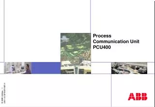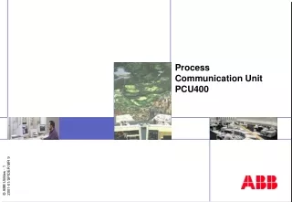
Data Acquisition Process Communication Unit PCU 400
Data Acquisition Process Communication Unit PCU 400. Network Manager. Network Manager - Data Acquisition. Facilitates Real-time Supervisory Control of Power Stations Substations Key information points in a distributed power network Development of Process Communication

Data Acquisition Process Communication Unit PCU 400
E N D
Presentation Transcript
Data Acquisition Process Communication Unit PCU400 Network Manager
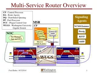
Network Manager - Data Acquisition • Facilitates Real-time Supervisory Control of • Power Stations • Substations • Key information points in a distributed power network • Development of Process Communication • Interfacing RTUs, SA- and IED-systems • Use of standardized protocols; WAN instead of leased line to the station • Deregulation leads to need for flexibility and versatility • IT-security • Data Communications • Redundant Solutions • Enterprise Wide • PCU400 is the solution for Network Manager
NG ZG WT 15 1 PCU400 as Front-End to Network Manager Application Servers Can be distributed over WAN RSP protocol over Ethernet LAN or WAN Functions: • Front-End for Network Manager • RSP protocol to Application Servers (AS) • Down line loading of database from AS • 1–24 multi-drop lines to RTUs • Protocol configurable per line • Various communication media • Distributed configuration is supported • Redundancy PCU400 Available RTU protocols RTU or SCS system
PCU400 PCU400 Distributed Functionality • The Data Acquisition System is distributed in two software components: • RCS Application • Supervision of PCU connection via TCP/IP comports • Handling of line switchover • Handling of redundant lines • Interfaces the SCADA application • Communication statistics • Handling of telephone connections and modem pools • Scaling of measurands • RSP Master • Database loading • PCU400 • Protocol translation • Time synchronization • RSP slave RCS Application
RSP Links PCU400 in Network Manager Main Server A Main Server B Other Applications Other Applications Real-time Database (Avanti) Real-time Database (Avanti) RCS Application RCS Application LAN or WAN PCU400 A PCU400 B RTU lines
PCU400 Mainframe • Industrial PC Chassis or Desktop • PCI slot, half or full length • Hard disc or Flash memory (embedded) • CDRW-device • Intel Pentium 4 compatible CPU • Minimum 256Mb Memory • Redundant Ethernet ports for Dual-LAN • Ethernet port for Communication Modules • Graphic card • Wall or 19” Rack-mount • PCU400 embedded version is without moving parts
Connectors available Parallell port PS2 keyboard/mouse USB 2 ports VGA COM1 and COM2 Powered by 24 V DC Ethernet to Host Optional 2 Ethernet and 4 COM ports PCU400 Embedded
PCU400 Embedded - specification • H6023-based (Hectronic), CPU is Geode GX1-300, 300MHz • 2 - 6 COM, 1 - 3 Ethernet • RAM 256MB • CompactFlash 256 MB - 1GB • Power 7-28V DC • Temperature range +5ºC to 45ºC • Size is about 220mm x 110mm x 77mm • Operating System Windows XP embedded • Option 1) Extended temperature range -40ºC to 80ºC • Option 2) Two additional Ethernet interfaces plus four additional COM-portsWith option 2 included a complete 6 channel PCU400 with redundant LANs is realized. A third Ethernet interface extends with more COM-ports using the OCC2 Communication HUB.
PCU400 Communication Module • Communication Module • 8 channels per unit, max 8 units per CPU (=64 channels) • 64 kbps per channel in parallel • Byte and Bit-sampling • Protocol support for Indactic33, Sinaut8, ADLP80 and asynchronous • Ethernet connection to PCU mainframe, allows distribution • DIN-mounted • DC powered
PCU400Communication Functionality • Asynchronous UART communication (speed 50 – 64000 bps) • Bit synchronous communication (bit sampling 50 – 4800 bps) • Dial-up (phone) Low level driver support of Hayes commands used with RP570 • RS232 (control signals supported) • LAN (single, dual), NetRAIN – Redundant Array of Independent Network adaptors (two interfaces appears using the same IP-address) • Security arrangement same as the operating system
Line Unit #x Line Unit #1 Line Unit #2 A A A B B B Ch. 1B Ch. 1A Ch. 2B Ch. 2A Ch. xA Ch. xB Communication Lines in Network Manager Database - Object level Line Pool # 1 = COM-line 1 Line Pool Line Unit #1 Line Unit #2 Line Unit #3 Hardware level LAN or WAN • Each Line Unit side is connected to a PCU number • The PCU can be distributed • Each RTU belongs to one Line Pool • Line switch only if redundant PCUs PCU # 1 PCU # 2 Line Switch Line 1, to RTU
Standard protocols (used in most projects) • IEC 60870-5-101 • ABB RP570 (use is decreasing) • IEC 60870-5-104 (use is increasing)
HUB Ethernet Ethernet Ethernet 1 2 3 4 5 6 7 8 1 2 3 4 5 6 7 8 1 2 3 4 5 6 7 8 PCU400 Hardware Assembly External or Internal
PCU400 Line Switch • Line Switch • 1 RTU line per unit • Speed up to 115 kbps • Connection to A and B system • Test connector for line analyzer • DIN-mounted • Redundant power input • Galvanic isolated B-side
Application Program Interface (API) for Openess • APIs gives flexibility to integrate protocol libraries • PCU400 optionally provides • A DDE interface • An OPC-client interface • An interface from ASE(USA-based company) • ABB will add more APIs • PCU400 users may add protocols using: • DDE • OPC • ASE • Toolkit
Schematic of Software Interfaces Control Center Communication FTP/HD RSP Plug-In Slave RSP bus XML Plug-In DDE OPC Master 3rd party LON 3rd party Engineering Tool (MS Excel) Process Equipment Communication
Operators Interface (device control) • Device in/out of service, status • Device restart • Redundant RTU line switching (active/passive) • Line unit switch (online/standby) • Communication statistics (4 counters) • Block/Deblock points
View and Test web-interface (option) • Commissioning of PCU400 • Test of database – I/O • Test of IED equipment
Local Control web-interface (option) • System overview • Station overview • Control • Event & Alarm list • Parameter Setting • Fault Distance Rec. Station Overview
Data Acquisition, Security 5 Application Server B Application Server A 4 RCS Application A RCS Application B LAN 1 2 LAN 2 RSP lines • Redundant PCUs • DualLAN • Line Unit, A and B side • Logging between RCS applications in a redundant system • Logging between Application Servers • …Connection if dual LANs 1 PCU400 A PCU400 B 3 3 RTU lines Line switch RTU
RCS Application, Time Synchronization Time base Application Server A RCS Application ASCII-string Minute pulses Cyclicbroadcast message(TSIL) (Y, M, D ,h, min, sec) PCU400 Time messages sent to RTU
PCU400, Time synchronization Clock Server Minute pulse PCU 400 Protocol Driver Time fetch via DLL Write the Time message to com board Write number of tics until sending should occur Dual ported memory Communication Board Time message Free running counter The board stops transmission until the tics are executed. Then sending occurs
NG ZG WT 15 1 REL 5x1 REC 561 PCU400 as Gateway for SA and SCADA systems Remote Master Systems Functions: • Data Gateway/Concentrator • Web-interface • Local Station Control • Local configuration via MS Excel • Allow connection to existing systems E.g. IEC 870-5-101 • Configuration Tool • WEB-interface • Local Control RTU orProtection relay
NG NG NG ZG ZG ZG NG ZG WT WT WT WT 15 15 15 1 1 1 15 1 REL 5x1 REC 561 PCU400 SA & SCADA Connectivity PLC Connect Network Manager Operate IT Industrial IT Medium Level High Level RSP XML OPC Base Level TCP/IP LON RTU protocol WEB-Interface PCU400 Gateway RTU
NG ZG WT 15 1 PCU400 asConverter Remote Master System Functions: • Connection of new RTU to old Master System • Connection of old RTUs to new Master System • One line to RTUs / Protection relays • Redundant lines to the Master system • Media converter (dial-up to leased line) • Local configuration E.g. IEC 870-5-104 Configuration Tool Example Connection of an RTU211 to an IEC870-5-104network by using the PCU400 embedded. E.g. RP570 RTU or SA system
OPC400 Server • API-Data Access 2.0 (DA) • API-Alarm and Event (AE) • All protocols will be available through the OPC-server • OPC Client also available Control Center Communication FTP/HD OPC DA OPC AE Slave RSP bus XML Plug-In DDE OPC Master Protocol 3rd part LON 3rd EXCEL Engineering Tool Process Equipment Communication
PCU400 Data Engineering • Local in PCU • COM-port definitions • Protocol per line (and characteristics) • Socket TCP/IP address and port • Runtime database Loaded via RSP or XML • Loaded per line from RCS Application (or via PCU400 internal X05 in case of XML) • Which RTUs on which lines • I/O for each RTU (logical and possibly physical)
NG ZG WT 15 1 PCU400 Data flow - SCADA Power System data SCADA Servers Data Engineering Tool Loading over LAN/WAN using RSP protocol File transfer to RTU if supported PCU 400
NG ZG WT 15 1 PCU400 Data flow - Gateway Power System data XML-files Configuration Tool MS Excel based PCU 400
Definitions in the PCU400 system • Basic configuration of the PCU400 • COM port • COM line • - Line unit • - TCP/IP port • - RSP address PCU 400
TCP/IP port and Comport LAN • The specification of the comport is done in the files linunit.ini and lu_xxx.ini • Following items defines the COM-port • COM-port number (1-255) • TCP-port (Socket connection to the PCU SW) Socket connection (TCP-port) PCU Software PCU Comport #1 RTU
Database Objects • Process Communication Unit (PCU) • Communication line (group of physical lines) • Line unit (physical line) • RTU • Scan group • Data types (AMV/DMV, IND, CMD, ACC, REG, SPV, GOM)
Frame type Datatype Length Sequence number Source line number Destination line number RTU number RSP Address • Each Line Unit is assigned to a RSP address • The RSP address is unique within the Comport • The RSP address is the same for Line Unit A & B side • Every node in a RCS system must have an address • The RSP address is within range 1 .. 255. Typically the following intervals applies: • [1..127] RTU lines • [128..199] Emulator lines • [200..255] Master Lines
Parameters in PCU400 Application Server PCU400 4) PCU general parameters RCS400.INI H99_INP.TXT H00.INI 3) Definition of lines and protocols LINEUNIT.INI SW bus (RSP) 2) General protocol settings H20.INI H14.INI 1) Line specific parameters, e.g., comport LU001.INI LU002.INI Indactic33 RTU’s RP570 RTU’s
Logging tools • Data traffic can be logged from • Local interface in Windows • Remote from a Telnet session via modem or network • Logging per communication channel • Logging of RSP traffic per PCU
PCU400 Installation • The PCU400 SW is installed from CD • Installation Wizard • Manual configuration of protocols and line data • Upgrade possible from CD or via network • Remote upgrade important in distributed systems
PCU400 Development tool • Standard software • Microsoft Development Studio 6.0 • Language C and C++ • Visual Source Safe • PC based • Portable for site assistance
RSP RSP Application Application Linklayer Linklayer Medialayer Medialayer PCU400, Protocol layers ABB Toolkit Basic Functions 3rd part interface RSP OPC client 3rd party OPC server
Windows XP WIN32 DCU Supervisor Watchdog Control Agent Remote config and logging Trap Manager Saving of Traps to HD Clock Server NT-Driver OCC / TCP-IP PCU400 Main Software Components