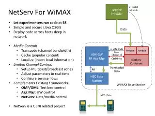
Base Station
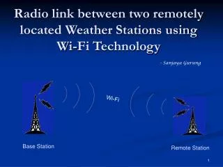
Radio link between two remotely located Weather Stations using Wi-Fi Technology. - Sanjaya Gurung. Wi-Fi . Base Station. Remote Station. Objective. To set up wireless link between: - Discovery Park_WS and EESAT - GBC Weather Station and Natural Heritage Center

Base Station
E N D
Presentation Transcript
Radio link between two remotely located Weather Stations using Wi-Fi Technology - Sanjaya Gurung Wi-Fi Base Station Remote Station
Objective • To set up wireless link between: - Discovery Park_WS and EESAT - GBC Weather Station and Natural Heritage Center • To collect data from all those stations via internet
Introduction Wi-Fi • Wireless Fidelity: • - Wireless Technology operating in 2.4 GHz and 5 GHz frequency band • Wi-Fi lies in Microwave frequency range: • 0.3 – 300 GHz (UHF - SHF - EHF) • Wi-Fi covers IEEE 802.11 (WLAN Standard) • Standard: IEEE 802.11 b/g: 2.4 GHz • IEEE 802.11 a/n: 5 GHz
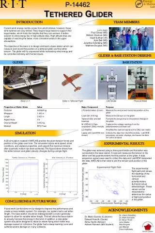
Radio Equipment • Ubiquity Networks Equipments NS2 • Nano Station Loco (Loco2) • NanoStation2 (NS2) • PowerStaion2 (PS2) Ethernet port Ext.Ant.
Radio Equipment (Contd..) • Comparison between three radio equips. of Ubiquity Networks
Radio Equipment (Contd..) • Data Rate Vs Receiver Sensitivity Data Rate Rx Sensitivity
Line Of Sight propagation • Clear LOS Very good RSL Tx Rx No obstruction for direct wave in LOS path Best reception at Receiver side (best RSL)
Line Of Sight propagation (Contd..) • Blocked LOS Very bad RSL Tx Rx Obstacle Other Obstacles: Buildings, high hills etc. lying between Tx and Rx antenna
Line Of Sight Impairments Signal Attenuation Friis Transmission Formula Pr(dBm)=Pt(dBm) + Gt(dB) + Gr(dB) – {FSL(dB)+At(dB)+Ar(dB)} Transmitting antenna gain Receiving antenna gain Received power Transmitted power Total LOSS FSL(dB) = 20log(f) + 20log(d) + 32.44 MHz Km FSL = Free Space Loss At = Transmission line loss between Tx and Tx antenna Ar = Transmission line loss between Rx and Rx antenna
Minimizing loss Signal Attenuation - Free Space Loss - Atmospheric Attenuation Free Space Loss FSL(dB) = 20log(f) + 20log(d) + 32.44 MHz Km f FSL d FSL
Minimizing loss (Contd..) Atmospheric Attenuation e.g: Heavy rain of 150 mm/hr At low frequency f = 2.4 GHz, A = 0.02 dB/km At higher frequency f >= 10 GHZ, A = db/km f Atm. Attenuation e.g: Dense forest having wet leaves At low frequency f = 3.0 GHz, A = 0.4 dB/m So there’s a huge path loss if signal passes hundred meters through the forest.
Radio Modeling EESAT – DiscoveryPark_WS
Range Extension Transmission distance can be increased by following ways: • Choosing low frequency …. but f = 2.4 GHz fixed • Increasing Tx power • External high gain/highly directive antenna • Use of Repeater f d PTx d G d
Repeater for longer transmission No sufficient power after this point R Tx 15 km 10 km Rx Repeater/ Signal Regenerator long link distance = 25 km (i.e. d > 15 km)
Repeater for LOS blocked signal R Signal is blocked Repeater Tx Rx
Minimizing Interference • Tx power • Channel selection • Polarization • Site selection
Minimizing Interference (Contd..) • Tx power • - Minimize Tx power to avoid interfering another channel nearby Rx Sensitivity (Rxs) - 92 dBm 10 km A B Z PRx Pz nearby channel PTx 26 dBm(=400 mW) - 60 dBm - 85 dBm If Pz > Rxs … interference 23 dBm(=200 mW) - 70 dBm - 95 dBm If Pz < Rxs … no interference
Minimizing Interference (Contd..) • Channel Selection • - Wisely selecting channel to reduce adjacent-channel interference Ch.1 Ch.6 Ch.11 Channel separation = 5 MHz 22 MHz Channel Bandwidth 3 non-overlapping (non-interfering) channels: Ch.1 = 2412 MHz Ch.6 = 2437 MHz Ch.11 = 2462 MHz
Minimizing Interference (Contd..) • Polarization • - Proper antenna polarization setting will significantly reduce interference from neighbouring interfering channel H A B H V Y V X
NS2 – Internet Connection Test EESAT_NS2 is connected to Router
Research Questions • How to avoid Line Of Sight (LOS) problem? • What parameters should be taken into considerations while choosing sites? • How to select appropriate radio equipments • How to minimize interference: using highly directional antenna • Trade off between Gain and Complexity in Antenna Alignment