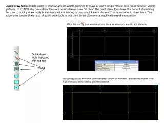

Quick-draw tools indicated with red dot
E N D
Presentation Transcript
Quick-draw tools enable users to window around visible gridlines to draw, or use a single mouse click on or between visible gridlines. In ETABS, the quick-draw tools are referred to as draw “at click” The quick-draw tools have the benefit of enabling the user to quickly draw multiple elements without having to mouse-click each element 2 or more times to draw them. The issue to be aware of with use of quick-draw tools is that they divide elements at each visible grid intersection Click this tool then window around the area where you want to add elements Quick-draw tools indicated with red dot Activating joints to be visible and selecting a couple of members (dotted lines) makes clear that members are divided at grid intersections
With SAP2000 or ETABS, use of the quick-draw area element enables users to quickly model elements by windowing around a selected area to draw separate area elements divided at each visible gridline. Fill option was activated using Set Display option button (aka ‘Set building view options’ in ETABS). Alternatively, users could click inside each bay one-at-a-time to draw areas using this draw tool . 4 areas in this example, divided at each grid intersection
Quick-draw bracing in elevation view using Inverted V bracing option. Bracing is added between each visible gridline within the windowed area
If you double-click any gridline in either SAP2000 or ETABS, you can modify grids, including the option to “Hide” from visibility. Note what happens when we try quick-draw modeling secondary beams based on 4 beam setting shown below right. Because the spacing between visible gridlines varies in this example because the B grid is hidden, the spacing of the beams vary too. There is another option on this draw tool to draw based on Max spacing. You can use this technique to model bracing or any other quick-draw option. In V14 of SAP2000, the hiding of gridlines is not recognized by the quick-draw tools (temporary bug). Secondary beams added
Other draw tools - So when do you use the draw tools which don’t have the red dots? Whenever you want to draw elements that do not coincide with or divide at visible gridlines or intersections with other elements. Draw frame tool can be used to draw beams, bracing, or columns. Below are some examples Bracing that spans multiple levels using draw frame tool Columns that span multiple levels or beams that span multiple grids Areas that span multiple gridlines so as not to distribute load to intermediate beams or bracing Using Draw areas tool Draw rectangular area tool lets you drag from one corner to another In this example, the columns will automatically mesh internally to account for the beams, but they will be reformulated to report and design as 1 column
Area finite element types - Shell type elements have both in-plane and out-of-plane stiffness which transfer both shear and moments. By default, shells transfer load two-way only at meshed joint locations. Membrane elements have in-plane stiffness only, and transfer shear load (not moments) as one-way uniform distributed load to beams. Plate elements have out-of-plane stiffness only. Since shell and membrane are predominantly used, we’ll limit discussion to those two types. In ETABS ( but not SAP2000), be aware that membrane type area elements are auto-meshed by default but shell type area elements are not. In ETABS, a “Deck” type area element is always a membrane type. A thick shell element includes transverse shear effects. In most applications involving concrete slabs, mat foundations, walls or steel tanks/vessels, thin shell is applicable. Membrane is used to model shear walls if the user wants to avoid wall out-of-plane stiffness, and when the load transfer from wall to floor is shear load only without moments. Membrane is also used to model floors which distribute shear load one-way without taking credit for the floor stiffness to resist moments from gravity loads. With ETABS, you must work with different object types. Deck object is always membrane. Other area objects give you a choice ETABS slab object lets you choose whether shell or membrane, and also gives choice of One-way load distribution, an option not currently available with SAP2000 shell type SAP2000 area type definition
Area meshing - Users have the option to mesh shell area elements to make them distribute load one-way as demonstrated below left using Edit>Edit areas in SAP2000 (Edit>Mesh areas in ETABS). In addition, users can use the modifier option to reduce stiffness in any direction. The modifier option can be used to specify reduced section for cracking, and/or reduced membrane stiffness if the engineer does not want to take credit for the slab or deck in-plane resistance to lateral loads. Reduced bending stiffness of shell to make it behave like a membrane. Shell will still transfer load only at meshed joint locations. Meshing as long strips forces 1-way load distribution with shell type areas
SAP2000 and ETABS offer several meshing tools. In addition to the 4X4, 2X8, etc. type of meshing, users can add gridlines or draw lines to help them more easily mesh area elements. In the example below, gridlines are added and then Edit>Edit areas in SAP2000 to mesh by Intersections of Visible gridlines as shown below right. With ETABS, when meshing floors, use “cookie cut” mesh options Add gridlines to help you mesh precisely where needed. Select area(s) to be meshed Edit menu>Edit areas in SAP2000. Similar options in ETABS
Use Set View options to activate Fill Objects to view mesh. Similar options in SAP2000, ETABS and SAFE Select 2 adjacent shell areas In this example below, only 1 shell area is meshed. Joints are automatically added to perimeter beams, but adjacent area shells need to be meshed in order to transfer loads at mesh points Use Edit menu again to mesh by gridlines
In order to assign different loads to different areas, to create openings, to assign a joint load or support, or transfer floor load to a beam or wall or column, you need to mesh for connectivity. One exception is with floor openings in ETABS. Floor openings in ETABS are drawn as an area with property “Opening” as shown below and ETABS will automesh. In SAP, floor openings are created by meshing and deleting areas. Wall openings are created by mesh and delete in both SAP2000 and ETABS With ETABS, use Edit menu to add reference planes and reference lines to help mesh vertical shear walls by gridline. With SAP2000, just add gridlines Mesh by gridlines Select a meshed area and press Del key on keyboard to create opening Select and delete for openings With ETABS, floor openings are drawn with this property
One of the most common meshing errors involves membrane type areas. Because membrane areas have no out-of-plane stiffness, each meshed floor membrane area needs to be supported at least one side by a beam. Wall membrane elements can take in-plane load, but not load normal to the element face unless there is support by beams or columns. ETABS tutorials encourage use of 1 large area floor element relying on automeshing. But with irregular floor structures, it may be better to draw and mesh the floor using Draw tools and Edit>Mesh options This membrane mesh will create instabilities since there are membrane areas unsupported by beams or columns Valid floor membrane mesh supported by beams on all sides Wall mesh needs to be carried through adjacent elements. Select joints and areas to mesh by “Selected Point objects on Edges” In this shear wall example, gravity loads are lumped at each support location. Long unsupported lengths of walls can act like beams. Mesh every 6 – 8 ft.’ or so (engineering judgment) and add supports along the base to more realistically model support conditions at the base of walls
In the wall example in the previous slide, it appears that ETABS only meshed adjacent elements. This may be a bug, but there’s an easy workaround. Activate Snap to perpendicular directions button, then Draw line (Draw frame/cable in SAP2000) with Property “None” and draw the line to continue the mesh through adjacent elements. Select the areas and the None property line and use Edit menu mesh option to mesh by “Intersections with selected line objects”. 2 areas and 1 line selected Now we have 4 areas after meshing based on selected line object Perpendicular snap
One important issue to note with regards to meshing is the application of the line constraint (called ‘edge constraint’ in SAP2000). The line constraint “zips” together adjacent elements which do not share common mesh points using a displacement interpolation numerical technique. By default, the line constraint is activated in ETABS, but in SAP2000 the edge constraint must be manually assigned. In the example below, we have a wall with a mismatched mesh. Select adjacent area elements and Assign>Area to activate or deactivate line/edge constraints. If joints of adjacent elements are reasonably close together, use of these constraints can be a huge time saver compared to manually adjusting the meshes, and it can save users from having to model transitions using less accurate triangular elements. Conversely, use of line constraints also gives results in a poorly meshed model which may be misleading, so use engineering judgment. Edge/Line constraint would solve this problem SAP2000 default ETABS default
By default, ETABS and SAP2000 automatically add joints to beam/frame elements for connectivity whenever adjacent area elements are meshed. Although joints are added for internal meshing, ETABS and SAP2000 reformulate the beam elements, keeping track of their physical length for reporting and design Joints are automatically added to adjacent beam elements
In order to have more control over which beam/frame members are transferred load when an area is meshed, users have the option to de-activate selected frames from taking load from area elements. Select frame elements that you do not want to take load and Assign>Frame to specify no automeshing Bracing is selected, then assigned not to automesh with floor SAP2000 ETABS
Select option menus are currently quite different between ETABS and SAP2000. For that reason, we’ll start by reviewing select options used by both programs. Holding down the left mouse key while moving the mouse right-to-left will select every element which is intersected, including those within the window. This enables users to utilize the width of the window to control what is selected. Users can switch from draw mode to select mode by pressing the Esc key on the keyboard or by clicking the Select arrow . Hold down left mouse key and drag right to left Assign selected joints, frames, and/or areas to groups. Later you can select by group to view, assign, or tailor output results Familiarize yourself with these 3 select options on your toolbar. Select all, previous selection (particularly useful when making multiple assignments to a selection), and clear selection. You’ll frequently need these options
Select menu options are fairly self-explanatory, except that SAP2000’s ability to select by tables opens a number of possibilities. In the following example, we will select only joints > or = 40 ft in the Z (vertical) direction which have load assignments from specified load patterns. First, we use the Select menu>Select>by Coordinate specification as shown.
Next, Select using tables to narrow down the selection further by choosing only joints which have load assignments from Ey and Wy load patterns which we highlighted. We’ll ignore the distributed loads for this example Joints now selected are only those equal to or above 40 ft which have Ey or Wy load patterns assigned to them Within Joint loads table, we select Current table within current selection Next, go back again to the Select menu and select Current table
Working with gridlines - In SAP2000, you start by defining perimeter grids, then double click any gridline to open the Define grids dialogue in order to add, delete, or modify gridlines and spacing in detail. Grids are quite useful in that they automatically generate planar views, and you can use grids to snap when drawing frames or areas. Also, grids can be added to help with area meshing since SAP2000 and ETABS offer the option to mesh by gridlines. If the “Glue to Grid Lines” option is checkboxed, elements modeled within a gridline that is modified will stretch or shrink with the change in grid spacing. Double-click any grid to display this dialogue. Here you can add, modify, and delete gridlines
With ETABS, you can define your grids in detail as soon as you start a new model.
Story levels add gridlines at each story elevation. If you want to add gridlines between story levels in ETABS, use Edit>Reference planes and reference lines. With SAP2000, you would simply add a Z gridline to accomplish this. Define story levels
Both ETABS and SAP2000 can have multiple Cartesian and/or cylindrical coordinate systems in one model. The “Convert to General System” option can be used if you need skewed direction gridlines.
This example will demonstrate the extrude feature as a modeling tool, as well as demonstrate a useful cylindrical grid feature within SAP2000. We define a cylindrical grid system as shown below, then use the quick-draw frames to add frame elements along the perimeter (section property doesn’t matter) at the top level.
Next, click the ‘select all’ button to select frame elements, then Edit>Extrude>Extrude lines to areas. In this example we extrude downward in the –Z direction 5 X 5 ft, deleting the dummy frames source object. This extrusion technique enables us to quickly model a cylinder made of area finite elements
By clicking the tz button you can unwrap the cylinder for editing as shown below left. In this example, we selected some areas and pressed the Del key on the keyboard to delete them in order to create an opening. If the tz button disappears, use the yz button to unwrap. ETABS does not offer this unwrap feature at this time.
We’re going to explore another option for modeling with extrude features which involves extruding points to lines. This modeling technique can be used to draw beams, columns, or braces, but it has a particularly useful application in drawing beams on a slope. In this example we divide selected beams, then select the newly added joints and Edit>Extrude points to lines (in SAP2000 Edit>Extrude>Extrude points to frame/cables). Window around joints to select SAP2000 offers the option to choose the section which is extruded. ETABS does not offer that option at this time.
Next after extruding the beam elements, use select options to select the extruded beams in order to rotate local axes and/or assign section. Use arctangent of the slope to determine angle, then Assign>Frame>Local axes and input angle. In this example, the sign of the angle changes at each level from positive to negative because of the alternating slopes. When working with concrete Tee sections in SAP2000, one peculiar aspect to defining the section is that you must first add from the steel section type and click Tee. Then simply change the default material from steel to concrete and input Tee section dimensions. View created by choosing extruded view and hiding gridlines then View>Create Open GL view in ETABS
Whenever a planar view is the active window, it’s displayed as a blue perimeter outline in the 3D model. In this manner, the windows are linked. In this screenshot, it’s an XY plan view at the top level, but using the arrow keys and xy xz yz buttons, users can switch views and scroll through the model. Click anywhere in a window to make it the ‘active’ window. The active window is indicated with a darker blue color header Switch ‘active’ window view using buttons highlighted below. Use Up/Down arrows to scroll through planar views
Users can work with up to 4 windows in either ETABS or SAP2000. When drawing sloped beams or ramps, users can begin drawing in one planar view window then complete drawing the element in another window which has a different planar location. When drawing ramps or sloped beams, it helps to work with 3 windows – 1 large 3D view with the other 2 windows in XY plan view but at different elevations.
‘Draw Point objects’ option in ETABS, aka ‘Draw special joint’in SAP2000, is a tool which enables users to draw joints offset a user specified distance from wherever they mouse click. It’s a useful tool for modeling irregular framing, sloped beams and columns, and assigning joint loads on frames. When drawing point objects on an existing frame element, ETABS and SAP2000 will automatically mesh that element internally in order to consider loads, but then reformulate the element to report results and design it using its original length with which it was originally drawn/modeled. Use point objects to model cantilevered structures Connect the dots to draw sloped columns or beams Use it to assign joint loads on existing frame elements Added a point here Clicking here with 4’ offset ETABS and SAP2000 automatically mesh this beam to account for joint loads, but report the beam as 1 moment diagram instead of dividing it into multiple smaller pieces Connect the dots to draw irregular spaced framing