Download
1 / 27
310 likes | 713 Vues
Learn the basics of antenna modeling using 4NEC2 software with step-by-step instructions, tools overview, and example models. Explore settings, editor options, and NEC programming structure for efficient antenna design. Enhance your understanding of RF theory and improve modeling skills to optimize antenna performance. Ideal for beginners and amateur radio enthusiasts.

E N D
Antenna Modeling With 4NEC2 Presented to HOTARC By Craig Weixelbaum May 22, 2014
Basic Modeling Approach using 4Nec2 The goals of this 30 minute presentation on 4Nec2: 1. Installation and basic set-up 2. Brief Discussion on NEC2 format 3. Basic modeling approach 4. Example model 5. Brief overview of some 4Nec2 tools What this presentation will not cover: 1. Method of Moments and RF Theory 2. NEC2 capabilities 3. All of 4Nec2 Features
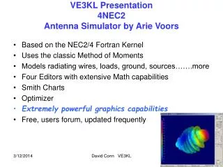
4Nec2 Overview Cost: $Free 3D Graphical Modeling program Uses the NEC2 Engine Platforms: Windows-95 to latest Windows-Vista 4Nec2 should work with Windows NT and Windows 7 Some documentation found says it works on Windows 8 Where to get 4Nec2 (As of 11Apr2014, Version 5.8.14):http://www.qsl.net/4nec2/
Installation Steps 1. Verify DirectX is version 8.0 or greater 2. From: http://www.qsl.net/4nec2 download “Latest 4nec2 version (5.8.14)” 3. Once installed verify that you can read the help file Readme.Txt file says possible problems with Windows-XP and -2000. If you have an install problem, check the readme.txt file for a solution. 4. Configure the Set-Up
Recommended Initial Settings • Select the Settings pull down menu and select the following options: • Auto Segmentation: 20 • Used for optimizer and sweeper functions. Reduce for memory concerns, increase for accuracy. • Input Power: 100 (Watts) • Input power used for voltage, current and field strength calculations • Char-impedance: 50 (ohms) • To set the characteristic line impedance for SWR plot and Smith chart
Recommended Initial Settings (cont) • Set the Reference System • Phi/Azim unit is the most traditional • Azim(compass)/Elev is the easiest to understand • Length: Inches • Radius: mm • I do not recommend changing any of the other default values until you have some experience modeling
The Editor • Each Editor has their own advantages. • Editors can be interchanged during the build of the model. Select the NEC editor (new) as your initial default editor
Editor Quick Overview • Notepad is the most basic and traditional way to program in NEC. Each line is typed in and is prone to card and format errors. Is the most flexible and allows using all of the NEC commands • NEC editor gives you more hands on control. Less likely to create card errors but format errors are still possible. • Geometry editor is a 3D modeler that makes antenna design more like drawing a picture. You do not need to know NEC card and format structure but adds to the learning curve. • NEC editor is best option for the beginner to start learning NEC.
NEC Overview • NEC is a stick-figure program. • Antennas & Structures are designed by wires. • Each wire has a unique number identifier call the Tag # • Wires are then broken down (by the software) into smaller segments • Segment sizes of λ/20 is typically a good start. • Keep your geometries as simple as possible. • Segmentation sizes do not have to be equal – but recommended. • Use smaller segments in critical areas and larger segments everywhere else • The segment length should be at least 4 times larger than the wire diameter. • The major limitation of NEC (and all modeling software) is memory space.
NEC Overview • NEC-2 use a 3 dimensional coordinate system to define antenna structure. • looking straight Up/Down is: • -- 90o if using Elevation • -- 0o if using Theta
NEC Overview • Solids • General rule, RF thinks that any gap that is smaller than λ/10 starts looking like a solid. • For 99% of all applications λ/20 is good enough • Antennas • Geometries and antenna structures do not have to be segmented to the same size. • Place antennas on Geometries at a wire ends. • Make sure wires touch!!
Voltage Sources • Each antenna that you want to “Radiate” needs a voltage source. • Voltage sources are placed within a segment – NOT AT THE ENDS • Voltage sources in NEC2 are “Ideal” • Use 1.0 for the magnitude and 0° for the phase. • For the majority of your modeling the voltage source will make no difference to the antenna pattern, gain or source impedance.
Voltage Sources (cont) • Voltage sources DO NOT contain a gap. They are assumed infinitely small in NEC2 • In the real world, an insulator is required.
NEC Program Structure • NEC uses “cards” for programming. • Cards need to be entered in a certain order
NEC Program Structure • Each NEC cards also have a specific format to follow
Steps to Model in NEC 1. Model the antenna(s) and structure(s) 2. Add the sources, loads, and ground data 3. Check Geometry and Segmentation 4. Run the simulation and review results 5. Tweak and re-run • 4Nec2 simplifies these steps through its user interface
4Nec2 Example • 40m ½ wave dipole antenna in free space (no ground) • Center Freq = 7.15 MHz • λ/2 = 300/freq/2 = 20.979m = 68.8288 ft • 14 AWG copper wire • 52 feet above ground
4Nec2 Example • Create the File • 1. Select EDIT on the 4NEC2 Main window then select Input (.nec) file • 2. Select File then New to begin editing a new model • Select the “Symbols” Tab • In the Scaling checkbox select “Feet” • Select File then “Save As” HOTARC_40m.NEC to name the new project
Adding Variables • Variables are not case sensitive “wire1” and “WirE1” are the same 1. In the symbols and equations column enter the following variables: height = 52 length = 68.83 feet wireSeg = 11 (notice the odd number) 2. Enter symbols for each of the wire end coordinates: PT1= (0, length/2,height) PT2 = (0, -length/2,height) • wireX1 = 0, wireX2 = 0, • wireY1 = length/2, wireY2 = -1 * length / 2 • wireZ1 = height, wireZ2 = height 3. Save the .necfile by selecting File then Save
Model the Geometry 1. Select the Geometry tab in the 4NEC2 Edit Window 2. Under “Type” select Wire - For Tag enter 1 NEC references wires by tag number Each wire requires a unique tag number - under Segs enter wireSeg - enter the coordinates of the wire ends x1, y1, z1and x2, y2, z2 wireX1, wireY1, wireZ1 wireX2, wireY2, wireZ2 - enter #14 for the radius (#14 is a predefined wire gauge symbol in 4NEC2 designating #14 wire) 3. Save the file
Model Sources and Loads 1. Select the Source / Load tab 2. Verify both Show Source and Show Loads are checked 3. In the Source Section: - For source select Voltage-src - Tag enter 1, Seg enter 50%, Real enter 1 For Seg you can choose 0% to 100% or a specific segment # 4. In the Loadssection: • Select wire conductor • Tag-nr enter 1, First-seg enter 0, Last-seg enter wireSeg • Select Cond then choose Copper 5. Save the file
Model Frequency and Ground 1. Select the Freq./Ground tab 2. Enter 7.150 in the Frequency cell 3. Select Real Ground in the Environment pull down - Select Rocky, steep hills in the Main ground NEC does not like things below the ground plane. 5. Save the file 6. Then close the Editor
Geometry and Segmentation Checking • Used to find many common modeling errors • Select the Geometry window • Verify the model displayed in the Geometry window looks like what you intended • Select Validate then select Run GeometryCheck • Select Validate select Run SegmentChecks • If there are errors go back to the Editor and make corrections!
Select the Output and Run the Simulation 1. Select Calculate from the 4NEC2 Main Window 2. Select NEC output-data 3. Select Far Field pattern 4. Select “FULL” 5. Set the resol to 5 degrees • Select Generate -- It is helpful to display the structure in the pattern window to see the pattern in relation to the antenna.
Convergence Testing • Used to check number of segments required for a good solution • I prefer a combination of impedance and gain
Additional 4NEC2 Tools • Geometry builder is used for making geometric figures that can be imported into your NEC file. • 2d Rectangle or Circle • Box, Cylinder, 3D Parabala • Sphere • Optimizer • GnuPlot for additional plotting -- download GnuPlot version 4.0 from the 4nec2 website