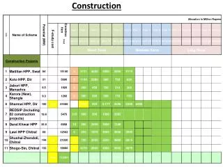
CONSTRUCTION
CONSTRUCTION The dc machines used for industrial electric drives have three major parts . Field system Armature and Commutator . Field system The field system is located on the stationary part of the machine called stator

CONSTRUCTION
E N D
Presentation Transcript
CONSTRUCTION • The dc machines used for industrial electric drives have three major parts. • Field system • Armature and • Commutator. • Field system • The field system is located on the stationary part of the machine called stator • and consists of main poles, interpoles and frame or yoke. • The main poles are designed to produce the magnetic flux. • The interpoles are placed in between the main poles. They are employed to • improve the commutation condition. • The frame provides mechanical support to machine and also serve as a path • for flux.
Armature • The armature is the rotating part (or rotor) of a dc machine. • It consists of armature core with slots and armature winding accommodated in • slots. • The conversion of energy from mechanical to electrical or vice-versa takes • place in armature. • Commutator • The commutator is mounted on the rotor of a dc machine. • The commutator and brush arrangement works like a mechanical dual • converter. • In case of generator it rectifies the induced ac to dc. • In case of motor it inverts the dc supply to ac. (In motor, the commutator • reverses the current through the armature conductors to get unidirectional torque).
OUTPUT EQUATION • The output equation relates the power developed in armature to the main • dimensions and speed of the machine. • The main dimensions of dc machine are the armature diameter, D and • armature length, L. • Power developed in armature, a = C0 D2L n • The output coefficient, C0 = ∏2 B_avacx 10-3 • Maximum gap density, Bg = B_av/Kf= B_av/Ѱ • C0 in terms of Bg is given by, C0 = ∏2 ѰB_gac x 10-3 • Power developed by the armature, Pa is different from the rated power output • P of the machine. The relationships between the two are • Pa= P/ɳ for generator • Pa= P for motors
CHOICE OF SPECIFIC MAGNETIC LOADING • The choice of average gap density or specific magnetic loading depends on • the following • Flux density in teeth • Frequency of flux reversal • Size of machine • Large values of flux density in teeth results in increased field mmf. • Higher values of field mmf increase the iron loss, copper loss and cost of • copper. • The Bav is chosen such that the flux density at the root of the teeth does not • exceed 2.2 Wb/m2. • If the frequency of flux reversals is high then iron losses in armature core and • teeth would be high. Therefore we should not use a high value of flux density in • the air gap of machines which have a high frequency. • It is possible to use increased values of flux density as the size of the machine • increases. • As the diameter D of the machine increases, the width of the tooth also • increases, permitting an increased value of gap flux density without causing • saturation in the machine. • The value of Bg varies between 0.55 to 1.15 Wb/m2 and the corresponding • values Of Bav are 0.4 to 0.8 Wb/m2
CHOICE OF SPECIFIC ELECTRIC LOADING • The choice of specific electric loading depends on the following • Temperature rise 2.Size of machine 3. Speed of machine 4. Armature reaction • 5. Voltage 6. Commutation • A higher value of ac results in a high temperature rise of windings. • The temperature rise depends on the type of enclosure and cooling techniques • employed in the machine. • If the speed of machine is high, the ventilation of the machine is better and • therefore, greater losses can be dissipated. Thus a higher value of ac can be used • for machine having high speed. • In high voltage machines, large space is required for insulation and therefore • there is less space for conductors. This means that in high voltage machines, the • space left for conductors is less and therefore we should use a small value of ac. • In large size machines it is easier to find space for accommodating • conductors. Hence specific electric loading can be increased with increase in • linear dimensions. • With high values of ac, armature reaction will be severe. To counter this, the • field mmf is increased and so the cost of the machine goes high. • High values of ac worsen the commutation condition in machines. From the • point of view of commutation a small value of ac is desirable. The value of ac • usually lies between 15000 to 50000 amp.cond/m
choice of number of poles • The frequency should lie between 25 to 50 Hz. • The value of current per parallel path is limited to 200 amps, thus the current • per brush arm should not be more than 400 amps. • Current per parallel path = Ia / p for lap winding= Ia /2 for wave winding • Current per brush arm = 2Ia / p for lap winding= Ia for wave winding • where, p = number of poles • The armature mmf should not be too large. The normal values of armature • mmfper pole are listed in Table below • If there are more than one choice for number of poles which satisfies the • above three conditions, then choose the largest value for poles. This results in • reduction in iron and copper.
Pole proportions • The cross-section of the poles should be circular in order that the length of • mean turn of the field winding is minimum. But circular poles cannot be • laminated, hence the next best alternative is square pole section. • In a square section the width of the pole body is equal to the length of the • machine. For square pole face, the pole arc (b) is equal to the length of the • machine. • L = b_p, for square pole section • L = b, for square pole face • Usually the ratio of pole arc to pole pitch or the ratio L/ is specified. • Ѱ= b/ τ= 0.64 to 0.72 • L/τ= 0.45 to 1.1
ARMATURE CORE DESIGN • The armature of a dc machine consists of core and winding. • The armature core is cylindrical in shape with slots on the outer periphery of • the armature. • The core is formed with circular laminations of thickness 0.5 mm. • The winding is placed on the slots in the armature core. • The design of armature core involves the design of main dimensions D & L, • number of slots, slot dimensions and depth of core. • Number of armature slots • The factors to be considered for selection of number of armature slots are • Slot width (or pitch) • Cooling of armature conductors • Flux pulsations • Commutation • Cost • A large number of slots results in smaller slot pitch and so the width of tooth • is also small. This may lead to difficulty in construction • But large number of slots will lead to less number of conductors per slot and • so the cooling of armature conductors is better.
If the air-gap reluctance per pair of pole is constant then the flux pulsations • and oscillations can be avoided. • It can be proved that the air-gap reluctance is constant if the slots per pole is • an integer plus 1/2. • For sparkless commutation the flux pulsations and oscillations under the • interpolemust be avoided. This can be achieved with large number of slots per • pole. • In fact, the number of slots in the region between the tips of two adjacent • poles should be at least 3. • The slots per pole should be greater than or equal to 9, for better commutation. • When large number of slots are used the cost of lamination and the cost of • insulation will be high.