Download
1 / 109
1.09k likes | 1.33k Vues

E N D
OBJECTIVESAfter studying Chapter 8, the reader should be able to:1. Describe the function of a vehicle’s transmission.2. Explain the operation of a manual transaxle.3. Discuss modifications made to automatic transmissions installed in hybrid electric vehicles (HEVs).4. Explain the operation of continuously variable transmissions (CVTs).
The transmission is the most complex component in the vehicle’s drive train, and is responsible for finding the balance between torque and speed during all phases of vehicle operation.
Transmissions and TransaxlesIn rear-wheel-drive (RWD) applications, it is most common to utilize a transmission in conjunction with a differential and final drive at the rear axle to transmit engine torque to the drive wheels.
In front-wheel-drive (FWD) applications, however, a transaxle is used to drive the vehicle’s front wheels.
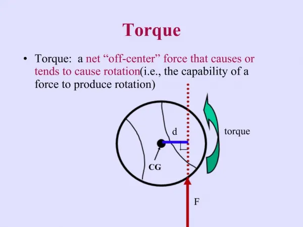
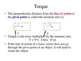
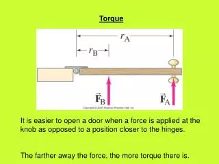
WHY A TRANSMISSION IS NECESSARYIn order to move a vehicle, torque must be applied to its wheels. Torque is twisting force. Applying more torque to the wheels will make the vehicle accelerate more quickly, but once a vehicle is up to speed, less torque is required to maintain that speed. The vehicle transmission is responsible for increasing engine torque in the lower speed ranges when acceleration is required, then reducing torque in favor of speed when the vehicle is cruising.
ICE produces zero torque at zero RPM, because the engine is not running. Zero RPM is when an electric motor produces the most torque.
It is difficult to keep the engine in this range during all phases of vehicle operation. Automotive engineers overcome this difficulty in two ways:1. By increasing the RPM range where the engine produces torque (“flattening” the torque curve). 2. By increasing the number of speeds in the transmission. With more transmission speeds, it is easier to match the vehicle speed with the engine’s most efficient RPM.
Speed versus TorqueWhen torque is increased in a transmission, output speed is decreased.
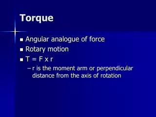
What Is the Difference between Horsepower and Torque?Torque is twisting force.Horsepower is the rate at which work is done, and is a function of torque and engine RPM. Horsepower can be calculated using the following formula:Horsepower = Torque × RPM 5,252
MANUAL TRANSAXLESThe manual transaxles currently being used in production hybrid electric vehicles (HEVs) are 5-speed designs. This means that these transaxles have five forward gear ratios and one reverse gear ratio.
Each gear position of the transaxle has a specific gear ratio (or speed ratio), which describes how fast the input shaft will turn relative to one turn of the output shaft.
Higher-Numbered Gear Ratios Are Used in Lower GearsThe first and reverse gears in a manual transaxle will have numerically higher gear ratios than any of the other gears. Is known as a reduction, because vehicle speed is reduced in favor of increased torque.Fifth gear in this same transaxle has a ratio of 0.71:1. In this gear, the transaxle input shaft will turn 0.71 turns for each turn of the output shaft. This is called an overdrive.
The primary function of the differential is to allow a difference in speed between the drive wheels on each side of the vehicle. This is necessary because the outside wheel in a turn must turn faster than the inside wheel.
The torque is then sent through the differential assembly and on to the drive wheels through the drive shafts (also known as half shafts).
Manual transaxles are most often built with four parallel shafts. These include the mainshaft, the countershaft, the differential, and the reverse idler. Most of the manual transaxles being built today are of the constant-mesh design.
The purpose of a synchronizer is to match the speed of the transmission shaft to the speed of the mating gear in order to prevent “gear clash” when selecting the gear.
How Are Gear Ratios Calculated?In order to calculate a gear ratio, take the number of teeth on the driven gear and divide it by the number of teeth on the drive gear. If a gear set has 13 teeth on the drive gear and 39 teeth on the driven gear, divide 39 by 13 to get a 3:1 ratio.# of teeth on driven gear ÷ # of teeth on the drive gear = Gear ratio
Synchronizers are operated by shift forks, which are attached to shift rails that are moved by the shift linkage.
The synchronizer assembly includes two synchronizer rings that are responsible for producing the “clutching” action that matches the speeds of the shaft and the required speed gear.
To reduce noise and increase gear strength, helical-cut gears are used.
This is different from a spur gear, which has teeth that are cut straight across and in line with the gear’s axis.
The final drive of a transaxle includes a drive pinion (small gear) on the countershaft driving a driven gear (large gear), which is attached to the differential carrier. This torque is transmitted to the differential gears, which are made up of two pinion gears attached to the differential housing by the pinion shaft, and two side gears that are attached to the drive shafts.
ServiceThe most important service procedure with any manual transaxle is fluid inspection and replacement.
Be absolutely sure to use fluids that have been approved for use by the vehicle manufacturer.
AUTOMATIC TRANSMISSIONSTorque ConvertersConventional automatic transmissions use a torque converter to couple the ICE to the transmission gear train.
The torque converter is attached to the ICE crankshaft through a flexplate. The basic torque converter contains three elements: the impeller, the turbine, and the stator.
Vortex flow takes place whenever turbine speed is less than 90% of impeller speed. During periods of vortex flow, the stator does not turn and acts as a reaction member inside the torque converter.
As vehicle speed increases, the turbine speed increases with it and eventually approaches the same speed as the impeller. At this point, the fluid flow in the torque converter changes from vortex flow to rotary flow, and the torque converter has entered the coupling phase.The speed of the turbine is now within 90% of the impeller speed, and very little torque increase is taking place in the torque converter.
Torque Converter ClutchesTo increase the efficiency of the transmission, the torque converter clutch (TCC) is applied and the turbine is locked to the torque converter housing.
Planetary GearsetsMost automatic transmissions use multiple (compound) planetary gearsets to produce the various gear ratios for each speed range of the transmission.
In order to make a planetary gearset transmit and modify torque, one of the members must be held, one must have input torque applied to it, and one must act as the output. To make all this happen, apply devices are used to either act as clutches or brakes. A clutch is a device that locks two elements together so that they both rotate at the same speed and torque is transmitted through them. A brake holds an element stationary so that it acts as a reaction member.
Apply DevicesA one-way clutch will allow rotation in one direction but not in the other. A one-way clutch is also known as an overrunning clutch.
A transmission band is used to hold rotating members and therefore acts as a brake. It is applied through the use of a servo, which is operated by hydraulic pressure.
The most common apply device used in modern automatic transmissions is the multiple- disc clutch.
Transmission PumpsThe pump picks up fluid through an inlet pipe and strainer located in the transmission oil pan. Since the torque converter housing turns with the ICE, hydraulic pressure from this pump is only available when the ICE is running.
Transmission ControlsThe apply devices in older transmissions were controlled using mechanical/hydraulic means alone, through a device known as a valve body that received inputs from throttle valves, vacuum modulators, and mechanical governors. Newer designs have incorporated electronic control to the point that virtually all transmission functions are determined by a transmission control module (TCM).
Adaptive StrategiesOne advantage of using electronic controls on an automatic transmission is that adaptive strategies can be utilized to make shifting smooth and consistent throughout the life of the transmission. As the clutches wear, it takes progressively more time for them to apply as more fluid is required to move the piston to the point of clutch application.
GM Silverado/Sierra Hybrid Automatic TransmissionDescription and Operation. The transmission in the Chevrolet Silverado/GMC Sierra hybrid pickup is based on the 4L60E electronically controlled automatic transmission design with minor modification to adjust for its new role in a hybrid power train. It has four forward speeds and one reverse, with the fourth speed being an overdrive.
This transmission was originally designed with mechanical/hydraulic controls only, but was later modified to incorporate electronic shift control.
Construction. However, changes were made to accommodate the addition of the integrated starter generator (ISG) inside the bell-housing assembly. The transmission was modified only to the extent where it was absolutely necessary, and otherwise used as much of the original design as possible.
The primary change was a decrease in the diameter of the torque converter in order for it to fit inside the rotor assembly of the ISG.
Whenever the engine goes into idle stop, the electric fluid pump is turned on to maintain oil pressure on the transmission’s forward clutch and keep the drive train connected to the engine.
Service. Transmission service for the 4L60E model M33 is limited to fluid and filter changes.
A scan tool can be used to access DTCs (diagnostic trouble codes) and also to perform bi-directional testing of the transmission solenoids. A scan tool can also be utilized for clearing the transmission adaptive pressure (TAP) values if any of the following has occurred:1. If the transmission has been overhauled or replaced2. Repair or replacement of an apply or release component (band, clutch, servo, piston, etc.) 3. Repair or replacement of a component that directly affects line pressure
Honda Accord Hybrid Five-Speed Automatic TransmissionDescription and Operation. Honda uses an automatic transmission (transaxle) in the Accord Hybrid that is similar to the ones used in its vehicles with conventional power trains.
The various speeds are selected through application of six multiple-disc clutches and a single one-way clutch.
The integrated motor assist (IMA) assembly is located between the ICE and the transmission. The torque converter drive plate (flexplate) is attached to the IMA rotor, which in turn is driven by the ICE crankshaft.