ALS Control and Electronics
ALS Control and Electronics. Michael Warner. 6-DOF Mirror Position Control. AOS Controls Øx, Øy, and z Sensors: Blend of 6 - 1um Mitutoyo Axial Gauges, and step counts on the 120 Axial Actuators. Actuators: 120 axial actuators, including 3 existing “hard points”. ALS Controls x, y, and Øz

ALS Control and Electronics
E N D
Presentation Transcript
ALS Control and Electronics Michael Warner
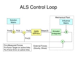
6-DOF Mirror Position Control • AOS Controls Øx, Øy, and z • Sensors: Blend of 6 - 1um Mitutoyo Axial Gauges, and step counts on the 120 Axial Actuators. • Actuators: 120 axial actuators, including 3 existing “hard points”. • ALS Controls x, y, and Øz • Sensors: 12 - 1um Mitutoyo Gauges, measuring radial position, and mirror rotation • Actuators: 6 lateral link actuators. • As the 2 control loops are orthogonal, their cross interactions should be small and controllable. • Will measure and model interactions during integration.
Mirror Position Control Block Diagram Measured Øx, Øy, z AOS Axial Control Loop M1 Mirror Steps Target Øx, Øy, z Position Forces ALS Lateral Control Loop Steps Position Target x, y, Øz Forces Measured x, y, Øz
AOS Position and Force Control Loop Measured Position Slow Loop Tip/Tilt Piston Inverse Influence Function Target Position Steps Forces Error Plane Integrate Gain M1 Mirror Target Forces Forces AOS Force Control Loop Steps Forces Actuators (Integrate) Fast Loop Measured Forces
AOS Influence Function ( FEA Model ) • Goodrich FEA model file ( Tur1fa4.dat), 117 Actuators with 1lb force, 3576 nodes measured. • The Influence Function used for converting CWFS OPD to forces (InfMatrix09102003.f2w) , is based on interpolation of the FEA 3576 nodes to a 25x25 CWFS grid for all the 120 actuators, points outside mirror are set to zero, the scale is um/lb. • 3 Hard points ( #42, #50, & #58 ) CWFS grids where set to zero. • The Influence Function used by the force loop, (InfluenceMatrix120.dat) is based on an interpolation of the 3576 FEA nodes to the 120 actuator locations, scaled to steps/lb. • 3 Hard Points columns set to zero. • 18.3 steps is added to diagonal for 117 other actuators to compensate for self influence. • FEA Model is producing large voids near the Hard Points, this is in error, as all 120 actuators do have a real influence.
FEA Model Surface Displacements Surface Displacement (um/lb) Surface Displacement Tip/Tilt Removed (um/lb) Surface Error (um RMS/lb) Surface Error Tip/Tilt removed (um RMS/lb)
AOS Influence Function ( Measured ) • A method was used to calculate the influence functions, based on actual force measurements, by using the following technique: • Each actuator was moved +200 and -200 steps, and all forces collected, for all the 120 actuators. • A matrix was constructed, and scaled in lb/step • The inversion of this matrix resulted in an equivalent of the theoretical InfluenceMatrix120.dat • The 18.3 step self influence was subtracted from the diagonal, this results in a matrix comparable to the FEA model, scaled in um/lb. • This surface displacement is similar to the theoretical one, a biggest difference is seen when the Tip/Tilt is removed, as the surface error clearly shows no voids near the hard points as expected.
Measured Surface Displacements Surface Displacement (um/lb) Surface Displacement Tip/Tilt Removed (um/lb) Surface Error (um RMS/lb) Surface Error Tip/Tilt removed (um RMS/lb)
AOS Position Loop Tests • The AOS Position Loop has been tested in open loop mode in order to minimize the Hard Point Force errors, with the following procedure: • A set of force measurements is made at different elevations angles, with the AOS in close loop, with a known Baseline file. • The hard point force errors at each elevation is used to calculate a tip/tilt/piston position error plane (20 steps/lb) • This position is multiplied with the inverse influence function in order to calculate a set of correction forces. • A polynomial of the correction forces v/s ZD is built and then added to the Baseline file used for the tests, this creates a tip/tilt/piston corrected Baseline file. • This procedure has been used successfully many times, with good results, as the hard points errors are always corrected with a single path.
ALS Position and Force Control Loop Measured Position Slow Loop M1 Mirror x, y, and Øz Target Position Steps Error Vector 3-Fixed Links Forces Gain Forces Target Forces ALS Force Control Loop Steps 3-Active Links Forces Fast Loop Measured Forces
ALS Force Control Loop 3 Active Link Target Forces: Link4 = -Link1 ~ 0 [Kg] Link2 = Link3 ~ +812.5*cos(ZD)/cos(30) [Kg] Link6 = Link5 ~ -812.5*cos(ZD)/cos(30) [Kg] Influence Matrix Limiter ( 10Kg max ) + 1 Stiffness Actuators (Integrate) Target Forces Gain X Steps - Loop Update Rate = 1 Hz Measured Forces
Measured ALS Influence Matrix • The Lateral Link Influence Matrix was measured by forcing +/200 Kg on each link and measuring the response on all links. • Influence matrix needs to be re-measured once new links are in place, to account for any stiffness changes Link1 Link2 Link3 Link4 Link5 Link6 Inf1 1.0000 -0.6514 0.0284 0.3117 0.0476 -0.6347 Infl2 -0.6866 1.0000 -0.6839 0.0117 0.3463 -0.0086 Infl3 0.0299 -0.6890 1.0000 -0.6728 -0.0729 0.3325 Infl4 0.3022 0.0138 -0.6252 1.0000 -0.6159 0.0101 Infl5 0.0350 0.3265 -0.0461 -0.6467 1.0000 -0.6635 Infl6 -0.7020 -0.0055 0.3448 0.0004 -0.7383 1.0000
Measured Lateral Link Stiffness Stiffness: Link1 = 4.03e6 Kg/m Link2 = 6.04e6 Kg/m Link3 = 6.29e6 Kg/m Link4 = 4.06e6 Kg/m Link5 = 5.57e6 Kg/m Link6 = 6.52e6 Kg/m
ALS Interface Speed requirements • Assumptions • Assume a El=90 deg to El=0 deg deg Telescope Motion • Maximum Force Error on Load Bearing Links ~ 300Kg ( from tests ) • Assume time to converge = 30 seconds max. • Assume a 7:1 lever ratio, and 80nm steps at actuator • Total Link stiffness = 4e6Kg/m or 4Kg/um ( 220,000 lbs/in ) • Derived requirements • Step Motion on Link = 80/7 = 11.4nm/step • Total Link Motion needed = 300/4 = 75um • Number of Steps = 75/0.0114 = 6578 steps • Max Step Speed = 6578/30 = 219 steps/sec • This is quite conservative and easy to implement with selected hardware, tested to 5000 steps/sec.
ALS Speed Requirements during Tracking • Calculation of worst case Control loop speed requirements: • Assume El at sidereal rate ( 15”/sec max ) • Maximum Force Rate of change: • sin (15”)*812.5/cos(30) = 0.0682 Kg/sec per link. • 812.5/cos(30) = Nominal Load on each link at ZD=90 • Step resolution at Link = 11.4nm, Link Stiffness = 4Kg/um • Force Step = 4 * 0.0114 = 0.0456 Kg/step • Max Speed = 0.0682/0.0456 = 1.5 step/sec • If we assume that a error of greater than 1Kg is needed before a correction is necessary, the loop needs to be updated at a maximum interval of 14.6 (1/0.0682) seconds, therefore an update rate of 1Hz for the control loop is more than adequate during tracking.
ALS Hardware Block Diagram SOAR Panic button ALS Electronics Box AOS Gravity 24V Power Supply Safety Interlock Compare Tilt Sensor Watchdog Timers G-load Ethernet 100 ADAM Module A/D ADAM Module RTD ALS Control S/W PC NI Field Point Digital RTD Sensors (6) Load Cells (6) RS-232 6x2 Step & Direction Mitutoyo Position Gauges (18) Force Step Motors (6) Step Motor Drivers (6) Existing Strain Gauges (24) Motors Brakes (6)
ALS Hardware Safety Interlocks • The ALS Hardware safety interlocks is designed to disable power to all actuators in case of hardware or software failure, with any of the following conditions: • Total Sum of all 6 link forces, shall be within +/- 100Kg • Sum of 4 load bearing links forces, when compared against a gravity sensor, shall be within +/- 100Kg • Each of the 4 load bearing link force, when compared against gravity sensor, shall be within +/- 100 Kg, this might have operational implications when moving the telescope at large elevation angles. • Each non-load bearing link force, shall be within +/- 100Kg • Watchdog timers will shut down system when software has lost communications for more than 1 second • Any ALS system power supply is out of range • External SOAR Panic Button
Harmonic Drive Systems Actuator • The LAH-80-520 Actuator, uses an Oriental Motors PK543AWM, 5-Phase Step Motor, with incorporated Brake. • Resolution = 80nm per step ( Motor has 500 Steps/rev ) • Maximum Load = 300Kg • Has an incorporated 50:1 Harmonic Gear
National Instrument Field Point Modules • The NI Field Point Units, will provide a safe and reliable Ethernet interface, for the generation of the critical actuator step motor step and direction commands. • The FieldPoint FP-1601 network module, connects the Ethernet network to the FieldPoint I/O modules, has a built in Watchdog Timer, for use in the safety interlock circuit • The FP-DO-400, 8-Channel, 5–30 V Digital Output Module will generate the actuator motor direction commands. • The FP-PG-522,8-Channel Pulse Generator with 2 A, 5–30 VDC Sinking Outputs, will generate actuator motor the step pulses. FP-DO-400 FP-PG-522 FP-1601
Oriental Motor 5-Phase Step Motor Driver • The CSD5807N-T 5-Phase Step Motor Driver, automatically applies current to the motor on power up. • The CSD5807N-T, has a standby hold current feature, set at 50% torque, is enabled 100ms after the last step. • Will receive the Step Pulse and Rotation Direction signals, from the NI Field Point Modules.
Advantech Ethernet I/O ADAM Modules • The ADAM modules provide a proven simple and robust interface with Ethernet connectivity. • The ADAM-6017, 8 Differential Analog Channels, 16-bit A-D Converter, Programmable Input range, 10 samples/ sec, 0.1% accuracy, 2 digital outputs, with built in Watchdog Timer, for use in the safety interlock circuit • The ADAM-6015, 7 Channel, 3 Wire RTD, 16-bit A-D Converter, 10 samples/sec, 0.05% accuracy.
VTI Technologies Tilt Sensor • SCA-111T-DO4 Inclinometer • Silicon 3-D MEMS Sensor • 0.1 deg accuracy • Simple 3 wire interface, +5V, Gnd and Analog Output. • The inclinometer signal output is directly proportional to the gravity vector, this will be used to compare against the sum of the 4 Load bearing Links. • Inclinometer Signal Output = K1 * sin(ZD) • Lateral Link Sum ( M2 + M3 - M5 - M6 ) = K2 * sin(ZD) • This sensor will be part in the first line of defense, against any motor or load cell failure.
Mitutoyo Position Indicators • Mitutoyo 543-692, 1um Indicator • 3um accuracy • 12.7 mm range • SPC Serial Interface to MIG-2A • MIG-2A Interface Electronics • Reads up to 8 gauges • Simple ASCCI protocol , RS-232 serial interface to host computer MIG-2A Interface
ALS Electronics Interconnect Diagram P1 ALS Electronics Box Motor Driver Box 1 MOTOR & BRAKE Link1 J1 P2 LOAD CELL & RTD J2 P3 Motor Driver Box 2 MOTOR & BRAKE Link2 J3 P4 LOAD CELL & RTD J4 P5 Motor Driver Box 3 MOTOR & BRAKE Link3 J5 P6 LOAD CELL & RTD J6 P7 Motor Driver Box 4 MOTOR & BRAKE Link4 J7 P8 LOAD CELL & RTD J8 P9 Motor Driver Box 5 MOTOR & BRAKE Link5 J9 P10 LOAD CELL & RTD J10 POWER 115VAC P11 Motor Driver Box 6 MOTOR & BRAKE Link6 J11 Ethernet P12 LOAD CELL & RTD J12
ALS Electronics Box Location M1 M6 M2 ALS M5 M3 M4