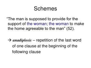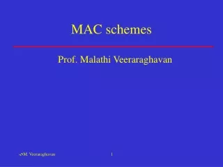
MAC schemes
MAC schemes. Prof. Malathi Veeraraghavan. Endpoint. Endpoint. Endpoint. Consider wireless links. Naturally broadcast medium One transmitter sends data; multiple receivers can receive the signal and obtain the data


MAC schemes
E N D
Presentation Transcript
MAC schemes Prof. Malathi Veeraraghavan
Endpoint Endpoint Endpoint Consider wireless links • Naturally broadcast medium • One transmitter sends data; multiple receivers can receive the signal and obtain the data • Need a MAC (Medium Access Control) protocol to share the “naturally broadcast” wireless medium
outbound Hub or optical passive star coupler inbound Host Host Host Multipoint drops: potential interference on inbound line – polling; e.g. multidrop telephone lines Hubs/Optical passive star couplers: any data received on one line is broadcast to all other lines Shared links in wired domain • Distance limitation between farthest hosts – Shannon’s capacity; SNR; attenuation
Shared links in wired domain • Ring networks: • ring adapters pass through the signal in cut-through fashion • hosts pick up data destined for themselves • Multitapped shared buses • in coaxial cable transmisison systems users can inject a signal that propagates in both directions of the medium Host Host ring adapter Host Host point-to-point transmission links Host
Classification of MAC protocols MAC protocols Fixed-assignment schemes Random-access schemes Demand assignment schemes Circuit-switched (e.g., FDMA, TDMA) Connectionless packet-switched (e.g., Ethernet, 802.11) Connection-oriented packet-switched (e.g., CDMA, polling) Channelization
FDMA (Frequency Division Multiple Access) • Similar to broadcast radio and TV, assign a different carrier frequency per call • Modulation technique determines the required carrier spacing • Each communicating wireless user gets his/her own carrier frequency on which to send data • Need to set aside some frequencies that are operated in random-access mode to enable a wireless user to request and receive a carrier for data transmission
TDMA(Time Division Multiple Access) • Each user transmits data on a time slot on multiple frequencies • A time slot is a channel • A user sends data at an accelerated rate (by using many frequencies) when its time slot begins • Data is stored at receiver and played back at original slow rate
Hybrid FDMA/TDMA TDMA Carrier Frequency Frequency Time Time Frequency vs. time FDMA Frequency Time Basic principle ofcommunication: Two regions in the time-frequency plane with equal areas can carry the same amount of information
Control aspect • How is the fixed assignment of a frequency and/or timeslot made? • Who makes it? • How long does an endpoint get to hold the frequency/timeslot? • Need a control channel on which stations can compete using a random-access protocol to obtain a channel assignment • Set aside control frequencies and/or timeslots
Endpoint Endpoint Endpoint Use of fixed assignment schemes on one shared link • All endpoints/hosts receive/transmit on common frequencies • many if FDMA is used • Use control channels to allocate frequency/timeslot for user communication between one pair • Release when done • In Ethernet hub, baseband transmission – 1 frequency – random access not fixed-assignment Hub or optical passive star coupler Host Host Host
On wireless links • Previous slide shows what’s referred to as an “adhoc” architecture • More common is to use an “infrastructure” based architecture • basestation or access point present
Internet Reverse channels Downstream Access points Upstream Forward channels Concept of upstream vs. downstream • Send data between endpoints via a basestation or AP • Can be placed at a height allowing all endpoints to see the basestation/AP • Endpoints that cannot “hear” each other communicate via the basestation/AP • MAC problem only in upstream direction PSTN Base stations/cell sites
A A B B 825 870 845 890 A A B A B 1 1 667 667 824 825 845 849 1 667 799 991 1023 Example of FDMA scheme:Advanced Mobile Phone System (AMPS) • FDMA/FDD • Spectrum allocation by FCC: A and B allocations to different providers Reverse Forward Original A A B A B Extended 869 870 890 894 1 667 799 991 1023
Duplex techniques • Separates signals transmitted by base stations from signals transmitted by terminals • Frequency Division Duplex (FDD): use separate sets of frequencies for forward and reverse channels (upstream and downstream) • Time Division Duplex (TDD): same frequencies used in the two directions, but different time slots
Impact of FDD • In AMPS, endpoints cannot “hear” each other • receivers at endpoints (phones) tuned only to downstream frequencies • adhoc mode essentially disabled!
D R Hexagonal cell frequency plan • D: Distance between • a base station and • the nearest base station that • uses the same channels • R: Radius of a cell • Reuse distance = D/R • Channel plan: method of • assigning channels to cells • to guarantee a minimum • reuse distance between cells that • use the same channel which is the minimum reuse distance for which
Reuse factor • Divide available channels into N groups • N: reuse factor; select N such that cells assigned the same frequencies will have a D:R ratio greater than (D:R)req • For hexagons, reuse factor N is given by • Practical values of N • range from 3 to 21 • most commonly used: 7 (D/R = 4.6)
Second example of fixed-assignment scheme: IS136 NA-TDMA • NA-TDMA is a hybrid FDMA/TDMA scheme • Therefore each frequency will have time slots that are shared by multiple calls • Typical: three calls share one frequency • NA-TDMA is three times as efficient • Same frequency allocation as for AMPS • Carriers are 30khz apart
1 2 3 The TDMA aspect: frames and time slots • Every frame is 40ms long and consists of 6 time slots • 1.9ms offset: allows a terminal to perform full-duplex communications without transmitting and receiving simultaneously • done to avoid a duplexing filter that separates strong transmit signal from weak receive signal base station to mobile 6 1 2 3 4 5 6 4 45 Mhz or 80 Mhz 1.9ms mobile to base station 6 1 2 3 4 5 6 1 2 3 4 5 40ms
Data rate of a carrier (frequency) • What is the data rate of a carrier (frequency) • Each time slot carries 324 bits • Data rate per carrier (frequency) • Four types of channels • A full-rate channel occupies two time slots per frame • data rate: 16.2kb/s • can have three times as many calls as in AMPS • per frame: 1, 2, 3, 1, 2, 3, 1, 2, 3,.... • Half-rate channel (8.1kbps), double full-rate channel (32.4kbps) triple full-rate channel (48.6kbps) • Voice calls carried within 1 full-rate channel (7.95kbps speech codec rate; channel coding rate 13kbps)
What about CDMA? • CDMA is not a fixed-assignment scheme • Concept of CDMA soft capacity • Allows more conversations to be packed in at the cost of quality of service • Many more codes can be assigned than there are frequencies/timeslots • My classification: CDMA is a demand-assignment scheme • postpone study to a wireless class
Random access MAC protocols • Comparable to connectionless packet-switching • No reservations are made; instead a wireless endpoint simply starts sending data packets • What can happen? • Collision • Need to avoid collisions or detect collisions and retransmit • What’s the cost of being too careful to avoid collisions? • Utilization will be sacrificed
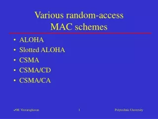
Various random-accessMAC schemes • ALOHA: just send & wait for ACK • Slotted ALOHA: send in slots • CSMA: sense carrier, but wait for ACK • CSMA/CD: detect collisions instead of waiting for ACK • CSMA/CA
ALOHA • Simplest scheme • True free-for-all. When a node needs to send, it does so. It listens for an amount of time equal to the maximum round trip delay plus a fixed increment. If it hears an acknowledgment, fine; otherwise it resends after waiting a random amount of time. After several attempts, it gives up. • Low delay if light load • Max. utilization: 18%
Slotted ALOHA • Competition to send only occurs at the start of each slot (equal to X) • Vulnerable period is X (not 2X as in ALOHA) • What is maximum throughput?
CSMA • Carrier Sense Multiple Access • sense carrier • if idle, send • wait for ack • If there isn’t one, assume there was a collision, retransmit • Vulnerable period: one tprop
Different techniques • 1-persistent: • if busy, constantly sense channel • if idle, send immediately • if collision is detected, wait a random amount of time before retransmitting • Non-persistent: • sense channel when station has a packet to send • if busy, wait a random amount of time before sensing again; • if idle, transmit as soon as it is idle • collisions reduced because sensing is not immediately rescheduled • drawback: more delay • p-persistent: combines 1-persistent goal of reduced idle channel time with the non-persistent goal of reduced collisions. • sense constantly if busy and the station needs to send a packet • if the channel is idle, transmit packet with probability p • with probability 1-p station waits an additionaltprop before sensing again
CSMA/CD • CSMA/CD: • In CSMA, if collision occurs, need to wait till damaged frames have fully propagated. For long frames compared to propagation delay, this could lead to significant waste of capacity. So add collision detection. • Rule: Frames should be long enough to allow collision detection prior to the end of transmission
Example of CSMA/CD: Ethernet • Ethernet (also 802.3) standardizes the 1-persistent CSMA/CD multi-access control protocol. • Each station listens before it transmits. • If the channel is busy, it waits until the channel goes idle, and then it transmits. • If the channel is idle it transmits immediately. Continue sensing. • If collision is detected, transmit a brief jamming signal, then cease transmission, wait for a random time, and retransmit. • collision detection is not by waiting for an ACK • Ethernet uses baseband transmission – one frequency
Collisions in Ethernet • The collision resolution process of Ethernet requires that a collision is detected while a station is still transmitting. • Assume: max. propagation delay on the bus is a.
Collisions in Ethernet • Restrictions: Frame should be at least as long as 2aR, where R is the transmission rate of the link, and a is the max. one-way propagation delay
Exponential Backoff Algorithm • If a station is involved in a collision, it waits a random amount of time before attempting a retransmission. • The random time is determined by the following algorithm: • Set “slot time” to 2a. • After first collision wait 0 or 1 time unit. • After i-th collision, wait a random number between 0 and 2 i-1 time slots. • Do not increase random number range if i=10. • Give up after 16 collisions.
Ethernet performance • f: fraction of time the channel is busy • L: length of frame; R: data rate • a: one-way propagation delay • 2ae: average number of contention slots before success in getting the medium; 2a is contention slot
Ethernet frame format Example MAC address: 04-3C-5A-11-26-78 Each four-bit half of each byte is expressed in hexa-decimal notation
Wireless 802.11 LAN • Uses CSMA/CA • Why CA and CD? • Difficult to detect collisions in a radio environment • Hidden station problem: • Two mutually far away stations A and C want to send to B. • At A and C, channel appears idle • But collision occurs at B
Mechanisms for CA • Use of Request-To-Send (RTS) and Confirm-to-Send (CTS) mechanism • When a station wants to send a packet, it first sends an RTS. The receiving station responds with a CTS. Stations that can hear the RTS or the CTS then mark that the medium will be busy for the duration of the request (indicated by Duration ID in the RTS and CTS) • Stations will adjust their Network Allocation Vector (NAV): time that must elapse before a station can sample channel for idle status • this is called virtual carrier sensing • RTS/CTS are smaller than long packets that can collide • Use of InterFrame Spaces (IFS)
CP CFP CFP Super-frame 802.11 MAC • IEEE 802.11 combines a demand-assignment MAC protocol with random access • PCF (Point Coordination Mode) – Polling • CFP (Contention-Free Period) in which access point polls hosts • DCF (Distributed Coordination Mode) • CP (Contention Period) in which CSMA/CA is used
DCFDistributed Coordination Function • This mode of 802.11 is a random access MAC • When a node needs to send data, it senses the medium. If idle, wait for a period of DIFS and if the medium is still idle after DIFS, send immediately. • If when the medium is sensed it is busy; then • wait for medium to be idle for a DIFS (DCF IFS) period • then decrement backoff timer until • medium becomes busy again; freeze timer, OR • timer reaches 0; transmit frame • if two stations have their timers reach 0; collision will occur; for every retransmission attempt, increase the contention window (CW), idle period after a DIFS, exponentially; 2i –1 starting with CWmin e.g., 7, 15, 31.
DIFS DIFS SIFS CW Random backoff time DCF mode transmission without RTS/CTS Data source Ack destination NAV other Defer access
DCF MAC • If medium was idle when sensed, send after waiting a DIFS period if medium is still idle after the wait • If medium was busy when sensed, wait for it to become idle. Then wait for a DIFS; then wait for a random backoff period called contention window - CW (because many stations may be waiting when medium is busy; if they all send the instant the medium becomes idle, or after exactly DIFS, chances of collision are high); sense at the end of CW. If still idle, send data
What frequencies are used in 802.11? • Frequency spectrum allocated for the ISM (Industrial, Scientific and Medical) unlicensed band • 2400 – 2483.5Mhz • 83.5 Mhz of bandwidth (US: starts 2.402Ghz to 2.480 – so 79) • 79 non-overlapping 1Mhz channels • Can 79 access points be collocated in one physical space unit and each use random-access MAC protocol to share a given channel? • Answer: no • Due to interference, only 26 can be collocated • Another dimension: Frequency hopping is used instead of a single frequency per AP
Frequency Hopping (FH) • What is FH? • Modulate the data signal such that it occupies different frequency bands as transmission progresses • e.g., send a song over many FM radio channels with some dwell time per channel • Why not use a single frequency per AP? • Multipath fading affects narrow frequency bands so that some channels offer very poor transmission • In FH, time spent in each channel is small
802.11 FH PHY • A channel hop occurs every 224 s • 78 hopping patterns • Divided into 3 sets of 26 patterns each • The sets are designed to avoid prolonged collision periods between hopping sequences in a set • Hopping patterns collide 3 times on average, and 5 times in the worst case over a hopping cycle; each hop is a jump of a minimum of 6 channels • Each 802.11 LAN must use a particular hopping pattern • The hopping patterns allow for 26 networks to be collocated and still operate simultaneously
Demand assignment schemes • Execute a call admission procedure to limit number of endpoints that simultaneously compete • Allow endpoints to take advantages of silences in each other’s transmissions to maximize utilization • Comparable to connection-oriented packet-switched networks • Examples • CDMA • 802.11 polling scheme
Shared link as a LAN:relation between MAC protocols and LANs • A shared link allows multiple end stations to hear a transmission from any station • No node is serving as a “forwarding engine” for packets in a controlled fashion • hubs, passive star couplers, ring adapters, taps blindly send data UNLIKE switches, routers, bridges • This shared link concept works well as a local area network • if too large a network – with many hosts – each host will get a small percentage of bandwidth
Shared links as “access” links • Two reasons for using shared links on the access segment • individual endpoints (hosts/phones) generate small quantities of data traffic • Costs should be kept low for end users • Consequence: access links are often shared • MAC protocols in the upstream direction
Shared link in the presence of basestations/APs? • Is it still one shared link if basestations/APs forward data between two endpoints that cannot “hear” each other • No, basestations/APs become forwarding engines, i.e., switches • If a cell phone under one basestation calls another cell phone under the same basestation and the basestation allocates frequencies for both ends and forwards data bits • Not different from a circuit switch forwarding bits received on one DS0 to another DS0 • Same thing when an AP uses destination addresses to rebroadcast data – it acts as a packet switch
Compare TDMA on an access link with TDM on an inter-switch link • Similar in concept: sharing resources on one link among many users • Difference: • Multiple senders on access link • One sender in each direction on inter-switch link Basestation Circuit switch Circuit switch T1 line carrying 24 different DS0s (phone calls) Endpoint Endpoint Endpoint Timeslot 1 Timeslot 2 Timeslot 3
Summary • Fixed-assignment schemes • FDMA, e.g. AMPS • TDMA, e.g., NA-TDMA • Random-access schemes • Aloha, slotted ALOHA, CSMA • CSMA/CD, e.g. Ethernet • CSMA/CA, e.g. 802.11 (Wi-Fi)