Miller Indices & Steriographic Projection
60 likes | 362 Vues
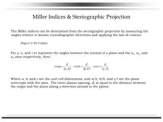
Miller Indices & Steriographic Projection. The Miller indices can be determined from the steriographic projection by measuring the angles relative to known crystallographic directions and applying the law-of-cosines. (Figure 2-39 Cullity).

Miller Indices & Steriographic Projection
E N D
Presentation Transcript
Miller Indices & Steriographic Projection The Miller indices can be determined from the steriographic projection by measuring the angles relative to known crystallographic directions and applying the law-of-cosines. (Figure 2-39 Cullity) For r, s, and t to represent the angles between the normal of a plane and the a1, a2, and a3 axes respectively, then: Where a, b, and c are the unit cell dimensions, and a/h, b/k, and c/l are the plane intercepts with the axes. The inner planar spacing, d, is equal to the distance between the origin and the plane (along a direction normal to the plane).
Vector Operations Dot product: Cross product: b a a Volume:
Reciprocal Lattice Unit cell: a1, a2, a3 Reciprocal lattice unit cell: b1, b2, b3 defined by: b3 B P C a3 a2 A O a1
Reciprocal Lattice Like the real-space lattice, the reciprocal space lattice also has a translation vector, Hhkl: Where the length of Hhkl is equal to the reciprocal of the spacing of the (hkl) planes Consider planes of a zone (i.e..: 2D reciprocal lattice). Next overhead and (Figures A1-4, and A1-5 Cullity)
Zone Axis Planes could be translated so as not to intersect at a common point.
C (hkl) dhkl H N B O f A Reciprocal Lattice (Zone Axis) Zone axis = ua1 + va2 + wa3