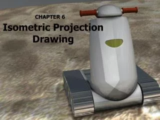
Isometric Projection Drawing
740 likes | 2.81k Vues
Isometric Projection Drawing. CHAPTER 6. Content. Overview Pictorial projection Parallel projection Axonometric projection Isometric projection Axes and selection Isometric lines and planes Isometric scale Isometric projection & Isometric drawing Producing Isometric sketches & drawing

Isometric Projection Drawing
E N D
Presentation Transcript
Isometric Projection Drawing CHAPTER 6
Content • Overview • Pictorial projection • Parallel projection • Axonometric projection • Isometric projection • Axes and selection • Isometric lines and planes • Isometric scale • Isometric projection & Isometric drawing • Producing Isometric sketches & drawing • Isometric lines & non-isometric lines • Circles and arcs • Irregular curves • Oblique projection drawing
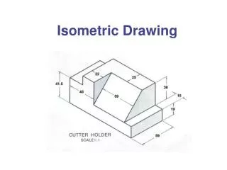
6.1Pictorial projection • Pictorial projection: • Not intended to give exact or true view. • Not intended to transmit dimensions, although sometimes dimension is useful. • Useful when the information and instructions to be given to non-technical and untrained people. • Hidden lines are not shown in isometric drawing.
6.1Axonometric projection • axon = axis; metric = measure, in Greek • Axonometric projection is a parallel projection technique to create a pictorial drawing of an object by rotating the object on an axis relative to a projection or picture plane
6.1Axonometric projection • Axonometric projection • Trimetric • Dimetric • Isometric
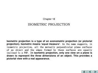
6.2Isometric projection • Isometric projection is a true representation of the isometric view of an object • Isometric view is created by rotating the object 45 degree about vertical axis, and tilting it forward 35 deg 16’
6.2Isometric projection: axes • The 3 axis meet at A,B form equal angles of 120 deg and they are called Isometric Axes • OA is vertical, OB is inclined at 30deg to the right, OC is inclined at 30deg to the left • Any lines parallel to these – Isometric Line • Any planes parallel – Isometric Planes
6.2Selection of Isometric Axes • Main purpose of isometric view is to provide a pictorial view which reveals as much detail as possible • Selection of principal edges is important • Figure shows different isometric views of the same block
6.2Isometric projection: scale • The tilt causes the edges & planes to become foreshortened • The projected length is approximately 80% of the true length
6.2Isometric projection & drawing • Isometric projection & Isometric drawing • Isometric projection: drawn at scale of 0.816 • Isometric drawing: drawn at full scale
6.3Non-isometric lines • Non-isometric lines are the lines that are not parallel to any of the iso-lines. • They are drawn by transferring the distance of X or Y from multi-view to iso-view, not the actual length itself. L L L is orthogonal not equal to L in isometric
6.3Isometric angles & non-iso lines • Example of producing non-isometric lines. • The position of point Z is obtained in the isometric view, by transferring the distance of X and Y.
6.3Iso-circles and arcs • Isometric circles or iso-circle cannot be simply drawn using compass. • Any iso-circle may lie on either top plane, left (front) plane or right (profile) plane. • Iso-circle looks slightly oval and skewed.
6.3Iso-circles and arcs: draw • Drawing isometric circles and arcs using four-centre method
6.3Producing isometric circle • Draw centre lines AOB and COD, O is centre of circle, AO=OB=CO=OD = radius of circle. • Draw FCG and EDH parallel to AOB, draw FAE and GBH parallel to COD. • Draw diagonal FOH, mark points J and K where FJ = HK = radius of circle. • With centre G and rad. R1 = GA, draw an arc between GJ produced at L and GK produced at M. Similarly with centre E. • With centres J and K and radius R2 = JL and KM, complete the figure.
6.3Iso-circles and arcs: draw • Drawing isometric circles using ordinate method.
6.3Drawing iso-circles 5 2 1 6 4 (a) • To draw an iso-circle, on left plane, Diameter 20mm • Draw centre lines, vertical & 30deg to left. • Draw (construction line) 20mm “square box”. The centre lines should divide each side by half. (b) 3 (c) 5 5 2 7 6 8 4 (e) (f) (d) (c) Draw straight lines; 1-2 & 1-3 and 2-5 & 2-6. (d) Point 7 is the intersection between line 1-2 & 2-5, and similarly point 8, 1-3 & 2-6 on the other side. (e) Set your compass to the distance 7-2, draw an arc with centre at point 7, from point 2 to point 5. Do the same on the other side. (f) Set your compass to the distance 1-2, draw an arc with centre (1), from (2) to (3).
6.3Irregular curves in isometric • Irregular curves in isometric are produced by transferring the coordinates from orthogonal view. • A fixed distance is set, A, and the distance in B direction are obtained. • These values are then transferred to the isometric view.
6.3Producing Isometric Sketches • Isometric drawing starts with isometric sketches. • Begin with defining isometric axis. • Begin sketch by extending axes – vertical lines, 30deg left & right.
6.3Producing Isometric Sketches • Sketch an isometric ‘box’. • Sketch the view on each faces, starting with isometric lines. • Add in non-iso lines and other details • Darken all visible lines.
6.3Iso-circles and arcs: sketch • Sketching iso-circle is simpler than drawing. • Create isometric square, each side=diameter. • Find the centre point and midpoints of each side. • Use the construction lines and point to sketch each quarter of the circle.
6.3Sketching isometric cylinder • Start by drawing the bounding box. • The front end of the cylinder is sketched using the previous technique. • The far end of the cylinder is a partial iso-circle. Sketch until meeting the tangent with the two straight lines.
6.4Producing Isometric drawing • Read the orthogonal drawing carefully, • observe the scale, • choose the best point where isometric axes meet to reveal as much detail as possible • draw an 'isometric box' enclosing the object • draw in light construction lines • draw arc & curves in thick, remove excess.. • line in 30 right lines • line in 30 left lines • line in vertical lines to complete the view
6.4Producing Isometric drawing • Read multi-view dwg given. • Observe scale, dimension, proj. angle • Determine front, side & top view. • Try to visualise how the object looks like. • Start with sketching, do not draw straight away. • If not sure, start with sketching an isometric box, enclosing the whole object. • You can label points, lines and surfaces on multi-view to help visualisation.
6.4Producing Isometric drawing • You can start drawing, once you’re able to visualise how the object looks like, or finish sketching. • Start with drawing construction line – draw the iso-box, and fill up with other lines. • Line in (darken) arcs & circles. • Line in iso-lines. • Line in all other lines.
6.5Isometric dimensions • Although isometric drawing is not intended to transmit dimension, sometimes dimensions are placed to indicate the size. • Two types:
6.5Isometric features • Common feature shown in isometric drawing. Screw thread (external) Fillet and rounds Isometric section view
6.6Oblique projection drawing • Oblique projection – parallel projection where the projectors are parallel to each other but not perpendicular to the projection plane
6.6Oblique projection drawing • The actual angle that the projectors make with the plane is not fixed, but preferably between 30deg – 60deg • Most common 45 degree
6.6Oblique projection drawing • 3 types: • Cavalier projection: true length along axis • Cabinet projection: half true length • General: any from half to full true length
6.6Oblique projection drawing • Place complex surfaces (arcs, holes, irregular curve, etc.) parallel to front plane • The longest dimension should be parallel to frontal plane
6.7Producing oblique sketch • First, sketch the front face. • Project 45 deg line to the back. • For holes, determine the visibility. • Line in all object lines.
End of Chapter 6 THANK YOU