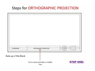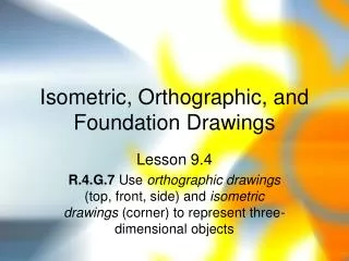
Orthographic Projection – Multi-View Drawing
Orthographic Projection – Multi-View Drawing. Orthographic Projection. a system of drawing views of an object using perpendicular projectors from the object to a plane of projection. Revolving an Object to Produce the Six Basic Views. Projection of an Object. The Glass Box.

Orthographic Projection – Multi-View Drawing
E N D
Presentation Transcript
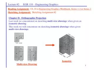
Orthographic Projection a system of drawing views of an object using perpendicular projectors from the object to a plane of projection
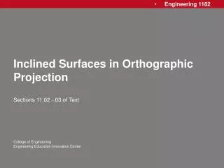
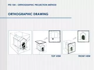
The Glass Box • Imagine that the object you are going to draw is positioned inside a glass box, so that the large flat surfaces of the object are parallel to the walls of the box. • From each pointon the object, imagine a ray, or projector perpendicular to the wall of the box forming the view of the object on that wall or projection plane.
The Standard Arrangement of Views TOP LEFT FRONT RIGHT BOTTOM REAR Why must views be arranged so that they align? To make it possible for someone to interpret the drawing.
Using a Miter Line to Transfer Depth 1. Draw miter line at 45 degrees at a convenient distance to produce the desired view.
Sketch light lines projecting depth locations for points to miter line and then down into side view as shown. 2.
4. Draw the view locating each vertex of the surface on the projection and miter line.
Symbols for 1st & 3rd Angle Projection Third angle projection is used in the U.S., and Canada
Other Visualization Tools • Number vertices in different views of multiview and isometric drawing • Practice
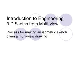
Multiview Sketching • Represents a 3-D object with a series of 2-D views in contrast to “pictorials” which show all three dimensions in a single view • Also called orthographic projection Multiview Drawing Pictorial
Parallel projection • Preserves true relationship between features • Lines that are parallel on the object are parallel on the drawing
Parallel versus Perspective Projection Parallel Parallel
Projection Planes versus Views • Projection planes: • Object formed from projection lines projected perpendicularly onto a projection plane • Planes: Horizontal, frontal, and profile • Each projection plane is perpendicular to adjacent projection planes • Principle views • The object is rotated 90 degrees about the horizontal or vertical axis to give six principle views (top, bottom, front, rear, left, and right side) • Common views: top, front, and right side
Only use Necessary Views • One view drawings • Sphere (Football) • Two view drawings • Cylindrical parts • Show the circular and rectangular view • Three view drawings • Usually sufficient for all other drawings • Top, front, and right side view
Orientation and Placement of Views • The most descriptive view should be selected as the front view • The natural orientation of the part should be preserved if possible • Views must be aligned • Top view above front view • Right view to the right of front view
Hidden lines • Represented with dashed lines • Precedence of lines (visible, hidden, center) • Views should be selected to minimize the use of hidden lines most descriptive view should be selected as the front view
Fold Lines • Represents a 90 degree fold between views • Generally not shown on engineering drawings except when views other than the principle views (auxiliary views) are used.
Terminology to Relate Views • Adjacent view • A view that is separated by a fold line • The top view is an adjacent view to the front view • Central View • A view that is between two adjacent views • The front view is the central view of the top, front, and right side view • Related views • Two views that are adjacent to a central view • The top and right side view are related views since they are both adjacent to the front view
Constructing a New View 2 • The top and front views of a surface are shown • The fold line represents a 90 degree fold between the views • Parallel projection lines are perpendicular to the fold line 1 3 1 3 2
2 1 3 1 1 3 3 2 2 Constructing a New View • A vertical fold line is drawn at an arbitrary distance from the front view • Parallel projection lines are drawn from each vertex • The common depth between the top and side view is used to locate each vertex on the projection lines
Sketching Allows for the Quick Translation of Thoughts to Paper • Commit thoughts to paper before you lose an idea • Avoid the of use mechanical tools (drawing tools are helpful for beginners) • Does not need to be an exact representation • objects may be simplified • parts may be missing • Avoid erasing • as new ideas are developed make new sketches • start with light lines and then darken with darker lead or heavier strokes
Summary • The six standard views are often thought of as produced from an unfolded glass box. • Distances can be transferred or projected from one view to another. • Only the views necessary to fully describe the object should be drawn.