Application Layer Multicast
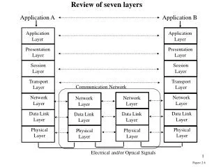
Application Layer Multicast. - Swati Agarwal. What Is Multicast?. Key: Unicast transfer Broadcast transfer Multicast transfer. Unicast One-to-one Destination – unique receiver host address Broadcast One-to-all Destination – address of network Multicast One-to-many

Application Layer Multicast
E N D
Presentation Transcript
Application Layer Multicast - Swati Agarwal
What Is Multicast? Key: Unicast transfer Broadcast transfer Multicast transfer • Unicast • One-to-one • Destination – unique receiver host address • Broadcast • One-to-all • Destination – address of network • Multicast • One-to-many • Multicast group must be identified • Destination – address of group Few slides are based on slides originally developed by (1) L. Armstrong, Univ of Delaware, (2) Rao -www.ibr.cs.tu-bs.de/events/netgames2002/presentations/rao.pdf
Example Applications • Video / Audio broadcast (one sender) • Conferencing (many senders) • Real time news distribution • Data distribution
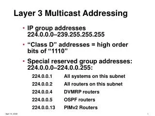
Routers with multicast support IP Multicast Gatech Stanford CMU Berkeley • Invented by S. Deering • Senders transmit IP datagrams to the group identified by a class D IP address • Efficient bandwidth utilization
Key concerns with IP Multicast • Deployment is difficult • Requires support from routers • Scalability • Routers maintain per-group state • Difficult to support higher level functionality • Reliability, congestion control
Application layer multicast Stan1 Gatech Stanford Stan2 CMU Berk1 Berkeley Berk2 Overlay Tree Stan1 Gatech Stan2 CMU Berk1 Berk2
Benefits • Scalability • Routers do not maintain per group state • Easy to deploy • No change to network infrastructure • Simplifies support for higher level functionality • Can utilize existing solutions for unicast congestion control
A few concerns.. • Performance penalty • Redundant traffic on physical links • Increase in latency • Constructing efficient overlays • Application needs differ • Adapting to changes • Network dynamics • Group membership – members can join and leave
Enabling Conferencing Applications on the Internet using an Overlay Multicast Architecture -Y. Chu, S. Rao, S. Seshan and H. Zhang
End System Multicast • Prior work show promising performance results • Studies based on simulations, static metrics, controlled environments • Can End System Multicast support applications with demanding performance requirements on Internet? • Study in context of conferencing applications
End System Multicast • Characteristics of the target applications • Small number of users • Require high bandwidth • Latency sensitive • Need for self-organizing protocols to adapt to dynamic latency and bandwidth metrics • Study in context of Narada Protocol • Techniques apply to all self-organizing protocols
Optimizing overlays for dual metrics • Prioritize bandwidth over latency • Member picks highest bandwidth path to every other member • If multiple paths with same bandwidth, pick the lowest latency path among those • Use exponential smoothing, discrete bandwidth levels to deal with instability due to dynamic metrics
Experimental Results Dip due to congestion stable
Comparison of schemes • Primary Set – 1.2 Mbps • Primary Set – 2.4 Mbps • Extended Set – 2.4 Mbps • Primary Set contains well connected nodes • Extended Set – more heterogeneous environment
Results - summarized • Enable optimized construction of efficient overlays • Random overlays perform poorly • Overlays adapting to static metrics perform poorly • Fail to react to network congestion • Both bandwidth and latency metrics need to be considered
Conclusion • Good performance for conferencing applications with stringent bandwidth and latency demands • Issues • Scalability - large groups • Adapting to highly dynamic environments
Overcast: Reliable Multicast • Provide scalable and reliable single-source multicast • Motivated by problems faced by content providers • Distribution of bandwidth intensive content on demand • Long-running content to many clients • Goals • Overlay structured to maximize bandwidth • Utilize network topology efficiently
Contributions • Storage at nodes for reliability and scalability • Simple protocol for forming efficient and scalable distribution trees that dynamically adapts to changes • Protocol allowing clients to join the group quickly
R Root Node Client Components • Root : central source (may be replicated) • Node : internal overcast nodes with permanent storage • Organized into distribution tree • Client : final consumers (HTTP clients)
R 1 R R R 1 2 2 1 2 Bandwidth Efficient Overlay Trees 1 100 Mb/s 10 Mb/s 100 Mb/s 2
Building Bandwidth Efficient Tree • Goal – maximize bandwidth to root for all nodes • Places a new node as far away from root as possible without sacrificing bandwidth • Nodes equally good if measured bandwidth within 10% • Select closest node as determined by traceroute
R R 1 2 3 The node addition algorithm 5 10 10 3 8 1 7 5 2 Overcast distribution tree
Dynamic Topology • Overcast’s optimization metric will change over time • A node periodically reevaluates its position in the tree by measuring the bandwidth between itself and • Its parent (baseline) • Its grandparent • All its siblings • Node can relocate to become • Child of a sibling • Sibling of a parent • Inherently tolerant of non-root failures • On dead parent a node can move up the ancestry tree
R R R 1 2 2 1 Interactions Between Node Adding And Dynamic Topology 10 20 1 15 2 Overcast network tree Round 1 Overcast network tree Round 2
State tracking – the Up/Down protocol • An efficient mechanism is needed to exchange information between nodes • Assumes information either • changes slowly (E.g., Health status of nodes) • can be combined efficiently from multiple children into a single description (E.g., Totals from subtrees) • Each node maintains state about all nodes in its subtree
Management of information with the Up/Down protocol • Each node periodically contacts its parent • Parents assume a child (and all descendants) has died if the child fails to contact within some interval • During contact, a node reports to its parent • Death certificates • Birth certificates • Extra information • Information propagated from children • Sequence numbers used to prevent race conditions
1.2.2 1.2.2.1 Scaling sublinearly in terms of network usage 1 • A node (and descendants) relocates under a sibling • The sibling must learn about all the node’s descendants • Birth certificates • The sibling passes this information to the (original node’s) parent • The parent recognizes no changes and halts further propagation No change observed. Propagation halted. 1.1 1.2 1.3 Birth certificates for 1.2.2, 1.2.2.1 1.2.1 1.2.3
Is The Root Node A Single Point Of Failure? • Root is responsible for handling all join requests from clients • Note: root does not deliver content • Root’s Up/Down protocol functionality can not be easily distributed • Root maintains state for all Overcast nodes • Solution: configure a set of nodes linearly from root before splitting into multiple branches • Each node in the linear chain has sufficient information to assume root responsibilities • Natural side effect of Up/Down protocol
The client side – how to join a multicast group • Clients join a multicast group through a typical HTTP GET request • Root determines where to connect the client to the multicast tree using • Pathname of URL (multicast group being joined) • Status of Overcast nodes • Location of client • Root selects “best” server and redirects the client to that server
R1 R2 R3 1 3 2 4 5 6 Client joins Key: Content query (multicast join) Query redirect Content delivery
Conclusions • A simple and bandwidth-efficient tree-building protocol • Dynamically adapt to changes • Scales to large networks – based on simulation studies