Application And Transport Layer Reliable Multicast
530 likes | 765 Vues
Application And Transport Layer Reliable Multicast. Leonard T. Armstrong University Of Delaware ELEG 667. Overview. What is multicast? Application-layer reliable multicast Overlay networks Case study: Overcast Transport-layer reliable multicast

Application And Transport Layer Reliable Multicast
E N D
Presentation Transcript
Application And Transport LayerReliable Multicast Leonard T. Armstrong University Of Delaware ELEG 667
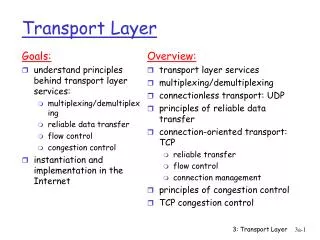
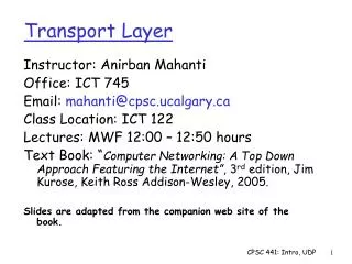
Overview • What is multicast? • Application-layer reliable multicast • Overlay networks • Case study: Overcast • Transport-layer reliable multicast • Multicast reliability using ACKs versus NAKs • Case study: PGM Some of the slides in this presentation are based on slides originally developed by (1) Ion Stoica, University of California, Berkley and (2) Sachin Kamboj, University of Delaware
Multicast Definition • “…multicast: the sending of a packet from one sender to multiple receivers with a single send operation.” • -- James F. Kurose, Keith W. Ross • Computer Networking – A Top-Down Approach Featuring the Internet
What Is Multicast? Key: Unicast transfer Broadcast transfer Multicast transfer • Unicast • One-to-one • Destination – unique receiver host address • Broadcast • One-to-all • Destination – address of network • Multicast • One-to-many • Multicast group must be identified • Destination – address of group
Multicast Application Examples • Financial services • Delivery of news, stock quotes, financial indices, etc • Remote conferencing/e-learning • Streaming audio and video to many participants (clients, students) • Interactive communication between participants • Interactive TV • Wireless entertainment • Delivery of content to a high volume of wireless devices • Bulk data transfer
Application-layer Reliable Multicast Overlay Networks And Overcast
Application-layer Multicast With Overcast • Overlay network • Single-source “multicast” • Uses HTTP for data transfer* • Primary metric – optimization of bandwidth • Specific to a certain set of application requirements • Only one data source – Is this limiting? • Large latencies acceptable • Nodes have large amounts of permanent storage • Not intended for interactive applications
What Is An Overlay Network? • Virtual network configuration • Set of nodes within an existing network fabric that implement a network abstraction on top of the underlying substrate network • Peers and their communication relationship form an abstract logical network • Requires no infrastructure change • Application-layer • Incrementally deployable • Do any popular applications use overlay networks?
GL KaZaA – File Sharing With An Overlay Network Key: Content query Query response File request File transfer • Distributed content location database • Some peers designated as group leaders (GL) • New peers are assigned a GL • Peers share content database with GL – GL only tracks content of peers in its group • Peer queries its GL who may forward request to other GLs • GLs send results of forwarded queries directly to the requestor GL GL GL
Benefits Requires no change to network infrastructure Incrementally deployable Network can be optimized to application-specific metrics Customizable – nodes may be multipurpose computers Uses off-the-shelf network technology for reliability, etc Burdens Management complexity Management from afar Management tools must not scale with network size Must consider connectivity limitations Firewalls, proxies Efficiency Need to deduce network topology Benefit/Burden Comparison Of Overlay Networks
R Root Node Client What Is Overcast? • Tree-structured overlay architecture • Virtual links of overlay tree are the only paths for data exchange • On-demand delivery of bandwidth-intensive content • Internet delivery of high-resolution video • Allows data to be sent once to many destinations • Draws upon work in content distribution, caching, and server replication • Comprised of • Root(s): central source (replicated) • Nodes: internal server nodes • Clients: end systems (HTTP clients)
Need to provide on-demand high-quality video to customer base Can’t count on multicast support of underlying network Only application-layer development is feasible Bandwidth bottlenecks develop as multiple requests are made Motivation Of Overcast Key: Line thickness indicates desired bandwidth usage by sending entity
Key Points • How can the root and nodes of an Overcast network be automatically configured? • Bandwidth-efficient trees • Dynamic topology • How can nodes maintain state (status) when configuration is automatic? • Eliminating the root node as a single point of failure • How can a client obtain content from an Overcast network?
R 1 R R R 1 2 2 1 2 Bandwidth Efficient Overlay Trees 1 100 Mb/s 10 Mb/s 100 Mb/s 2
How Does Overcast Build Bandwidth Efficient Trees? • Goal – maximize bandwidth to root for all nodes • Places a new node as far away from root as possible without sacrificing bandwidth • View algorithm • Additional details • Bandwidth: measured by timing a 10KB download • Improved techniques are planned • “”: Defined as “no more than 10% higher than” • SelectClosest: determined by traceroute • Won’t the results of this algorithm change over time?
R R 1 2 3 Result Of The Node Adding Algorithm 5 10 10 3 8 1 7 5 2 Physical network substrate Overcast network tree
R R 1 2 3 Result Of The Node Adding Algorithm – A Clearer Animation 5 10 10 3 8 1 7 5 2 Physical network substrate Overcast network tree
R R 1 2 3 Sourabh’s Question Will The Link Before A Leaf Always Have The Lowest Bandwidth? 5 10 10 3 20 1 7 5 2 Physical network substrate Overcast network tree
Dynamic Topology • Overcast’s optimization metric will change over time • A node periodically reevaluates its position in the tree by measuring the bandwidth been itself and • Its parent (baseline) • Its grandparent • All its siblings • Node can relocate to become • Child of a sibling • Sibling of a parent • Inherently tolerant of non-root failures • On dead parent a node can move up the ancestry tree
R R R 1 2 2 1 Interactions Between Node Adding And Dynamic Topology 10 20 1 15 2 Physical network substrate Overcast network tree Round 1 Overcast network tree Round 2
State Tracking – The Up/Down Protocol • An efficient mechanism is needed to exchange information between node • Must scale sublinearly in terms of network usage • May scale linearly in terms of storage • Assumes information either • Changes slowly (E.g., Health status of nodes) • Can be combined efficiently from multiple children into a single description (E.g., Totals from subtrees) • Each node maintains state about all nodes in its subtree
Management Of Information With The Up/Down Protocol • Each node periodically contacts its parent • Parents assume a child (and all descendants) has died if the child fails to contact within some interval • During contact, a node reports to its parent • Death certificates • Birth certificates • Extra information • Information propagated from children • Sequence numbers used to prevent race conditions
1.2.2 1.2.2.1 Scaling Sublinearly In Terms Of Network Usage 1 • A node (and descendants) relocates under a sibling • The sibling must learn about all the node’s descendants • Birth certificates • The sibling passes this information to the (original node’s) parent • The parent recognizes no changes and halts further propagation No change observed. Propagation halted. 1.1 1.2 1.3 Birth certificates for 1.2.2, 1.2.2.1 1.2.1 1.2.3
Is The Root Node A Single Point Of Failure? • Root is responsible for handling all join requests from clients • Note: root does not deliver content • Root’s Up/Down protocol functionality can not be easily distributed • Root maintains state for all Overcast nodes • Solution: configure a set of nodes linearly from root before splitting into multiple branches • Each node in the linear chain has sufficient information to assume root responsibilities • Natural side effect of Up/Down protocol
R1 R2 R3 1 3 2 4 5 6 Fault-tolerant Root Node Structuring Contains state of {1, …, 6} Contains state of {R2, R3, 1, …, 6} Contains state of {R3, 1, …, 6}
The Client Side – Joining A Multicast Group • Clients join a multicast group through a typical HTTP GET request • Root determines where to connect the client to the multicast tree using • Pathname of URL (multicast group being joined) • Status of Overcast nodes • Location of client* • Root selects “best” server and redirects the client to that server
R1 R2 R3 1 3 2 4 5 6 How Should Client Join Requests Work? Key: Content query (multicast join) Query redirect Content delivery
Redirecting To The “Best” Server • “Seamlessly Selecting The Best Copy From Internet-Wide Replicated Servers” – three methods • 1. HTTP redirect • Central server accepts and redirects query to an alternate server using “HTTP REDIRECT” • 2. Domain Name Service (DNS) round trip times • Local name servers track RTT of requests to other servers • Favors servers that are faster (closer) • Different name servers can serve different IP addresses for a common name • 3. Shared IP Address • Illusion of a single logical machine connected in several places • Suspect Overcast uses a combination of HTTP Redirect, DNS
Is Overcasting Multicasting? • HTTP TCP unicast! • If a node has n children, n separate TCP connections are used • Multiple unicast • Seems more like a contribution to smarter content distribution systems than to multicasting • “Application-level multicast… uses unicast transmission but involves the receivers in the replication and forwarding of data.” • Computer Networking – A Top-Down Approach Featuring the Internet • James F. Kurose, Keith W. Ross
Multicast Network traffic scales well Source transmits single packets which are duplicated by routers Multicast-enabled infrastructure Common group destination address Multiple Unicast Network traffic ~ group size Source transmits multiple packets – no router duplication No infrastructure requirement Each packet intended for a specific unicast destination address Multicast Versus Multiple Unicast
Transport-layer Reliable Multicast Pragmatic General Multicast (PGM)
What is PGM? • Pragmatic General Multicast • Was “Pretty Good Multicast” • Name changed c. 2000 because “Pretty Good” is a registered trademark!?! • Reliable transport protocol • Primarily ARQ-based • FEC support is optional • Defined in RFC 3208 • Invented by TIBCO, bought by CISCO
Transport Layer Multicast With PGM • Reliable transport protocol • Other reliable transport-layer multicast protocols include: • RMP – Reliable Multicast Protocol • RMTP – Reliable Multicast Transport Protocol • MFTP – Multicast File Transfer Protocol • Relies on lower-layer multicast protocols • IP multicast for best effort (unreliable) datagram delivery • Internet Group Membership Protocol (IGMP) for multicast group membership • NAK-based protocol
PGM Services • Multicast data delivery from multiple sources • Multiple senders multiple receivers • Specification and presentation will focus on single-sender • Reliable • Data integrity (checksums) • Receivers receives all data packets or… • Receivers able to detect unrecoverable packet loss • No-duplicate packets • Ordered or unordered delivery • Sender has no knowledge of receiving group membership
Components Sender Receivers Network elements (NE) Routers May or may not be PGM-capable Sender-to-receiver packet types ODATA – original data RDATA – repair data Source path message (SPM) NAK confirmation (NCF) Receiver-to-sender packet types NAK PGM Basic Building Blocks
IP Multicast Primer • Groups defined using class D addresses • 224.0.0.0/4 228 groups • Distance Vector Multicast Routing Protocol (DVMRP) • Source-based trees: each source node is the root of its own distribution tree • Reverse-path forwarding: received packets are forwarded out all interfaces except the packet’s incoming interface ONLY if the packet was received on the interface that is on it’s own shortest path back to the sender • Packets from a given sender only travel down the sender’s source path tree • Protocol Independent Multicast (PIM)
ACKs In Multicast – ACK Implosion Key: Multicast send ACK • Assume • ACK-based multicast protocol • Multicast group of n members • Each packet gets multicast to all n members • All members acknowledge receipt with a positive ACK • N ACKs are returned to sender for each packet sent • Sender is overwhelmed by ACKs • Result – ACK implosion • ACK-based protocols do not scale well for multicast
ACK Versus NAK • Reliability is accomplished through confirmation of data from receiver to source • Positive acknowledgements (ACK)… • Frequency is a function of the number of packets transmitted • Used in TCP for transmission buffer management (congestion control) • Negative acknowledgements (NAK)… • Frequency is a function of network reliability
NAKs To The Rescue Key: Multicast send NAK • NAKs inform sender of lost data on an as-needed basis • Scale with problems in network, not with size of group • Sequence numbers signal lost packets to receivers • NAK-based protocols work best when • Network reliability is high • Data is sent frequently Drop
NAK Implosion Key: Multicast send NAK • Assume • NAK-based multicast protocol • Multicast group of n members • Data packet can get lost at any point including first hop out of source • Result – ACK implosion • PGM takes precautions to prevent NAK implosion Drop
NAK And NCF Use • NAK – unicast UP the tree toward the sender • NCF – multicast DOWN the tree toward all NE descendents • Sent from NE but uses source address of original sender to insure correct path traversal • Strategies to lessen NAK burden • NAK suppression • NAK elimination
NAKety-NAK, Don’t NAK Back • NAK suppression • Receiver waits a random time before sending NAK – does not send if corresponding NCF is heard • Random delays should be proportional to number of PGM siblings • Increase probability of hearing NCF as a result of a NAK from another node with common ancestor • Supports optional multicasting of NAK with TTL=1 • Other nodes receiving NAK suppress their NAKs • NAK elimination • Parent NE aggregates or eliminates NAKs before propagating up the tree • Parent NE forwards at most one NAK per packet
Source Path Messages Key: Multicast send NAK • Determine next upstream hop for reverse path • Continual update of next upstream hop info when path changes • Establish source path state in PGM NE • Prompt detection of missing packets in the absence of data to transmit • Compensate for short or slow data flows
Components Of A PGM Network • Source – originator of data packets • Receiver – consumer data packets • Network elements • PGM-ready routers present in the intervening network • Unlike other transport layer protocols that only deal with end-to-end communication, PGM requires PGM compatible routers • Non-PGM routers may be part of the intervening network
Receiver A detects lost packet, NAK to 1st hop PGM NE NCF from 1st hop PGM NE Propagated NAK to upstream PGM NE NCF from upstream PGM NE Propagated NAK to upstream PGM sender NCF from sender Receiver B detects loss of same packet, NAK to 1st hop PGM NE NCF from 1st hop PGM NE, no further propagation of NAK PGM Operation Under Loss A B
PGM Network Elements Source Host Destination Host • Traditional transport-layer protocols • End-to-end communication • Not present in intermediate NEs • PGM • PGM NEs need transport-layer PGM code • Give special treatment to SPM, NCF, RDATA • Transmitted with IP router alert • Non-PGM NEs allowed – operation of protocol is less efficient Network Elements Application Application Transport Transport Network Network Network Network Link Link Link Link Physical Physical Physical Physical Non-PGM PGM Application Application Transport Transport Transport Network Network Network Network Link Link Link Link Physical Physical Physical Physical
Undiscussed (Optional) PGM Concepts • Designated local repairer (DLR) • Used to send RDATA “locally” rather than having the RDATA come from the original source • DLR is one hop from NE for which it provides “local” RDATA • Forward error correction (FEC) • Sends h additional parity packets for every k data packets (“transmission group”) sent • Receiver is able to reconstruct the original k data packets from receipt of any k of the h+k sent packets • Result: tolerance of up to h packet losses • PGM supports pro-active or on-demand FEC
How Well Does PGM Perform? These figures do not account for losses and/or forward error correction (FEC).
Problems Inherent With NAK-based Approaches • TCP does not move it’s trailing cwnd window edge until the data packet at the trailing edge has been successfully ACKed • What problems could occur in a NAK-based system, relative to trailing window edge and why/how could they occur?