Download
1 / 20
200 likes | 391 Vues
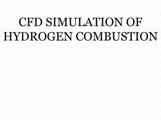
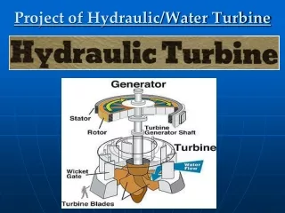
CFD simulation of flow field in a hydraulic turbine 2008-05-20 Meeting KTH SWECO TURAB. SEE MSc. Thesis. Overview of the Project Work Flow . Project Timing . Project Approach . 3 Main parts Structured meshing Using symmetry in mesh generation. G.V. B.R. D.T. Meshing of Guide Vane .

E N D
CFD simulation of flow field in a hydraulic turbine2008-05-20 MeetingKTHSWECOTURAB SEE MSc. Thesis
Overview of the Project Work Flow Project Timing
Project Approach • 3 Main parts • Structured meshing • Using symmetry in mesh generation G.V B.R D.T
Meshing of Guide Vane • Modified G.V geometry & opening angle
Meshing of Guide Vane Passage geometry Passage mesh O-grid around GV
Meshing of Guide Vane- Solution • Method 1
Meshing of Guide Vane- Solution • Method 1 • Method 2
Meshing of Guide Vane- Solution • Method 1 • Method 2 • Method 3
Meshing of Blade Runner Defining passage Symmetric passage Passage mesh
Meshing of Blade Runner • Animation 1 • Animation 2
Next Steps • Exporting the meshes to the solver (Fluent) • Taking a down to top approach (part to total) • Each passage and part will be solved with inlet mass flow boundary condition seperatly • ? Using pridiodicity for 3 G.V+4 B.R then apply the outlet as the inlet of D.T
Open questions • Confirmation of the B.R spatial location relative to the rotor shaft • CFX Turbo instead of the Fluent • Turab factory+site visit