Download
1 / 73
730 likes | 949 Vues
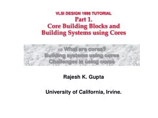
VLSI DESIGN 1998 TUTORIAL Part 1. Core Building Blocks and Building Systems using Cores. What are cores? Building systems using cores Challenges in using cores. Rajesh K. Gupta University of California, Irvine. Available “Core” Building Blocks. 68030. ARM810. PPC401.

E N D
VLSI DESIGN 1998 TUTORIALPart 1.Core Building Blocks andBuilding Systems using Cores • What are cores? Building systems using cores • Challenges in using cores Rajesh K. Gupta University of California, Irvine.
Available “Core” Building Blocks 68030 ARM810 PPC401
What Is A Core Cell? • Working definition • at least 5K gates • pre-designed • pre-verified • “re-usable” • Examples: • Processor: LSI logic CW4001/4010/4100, ARM 7TDMI, ARM 810, NEC 85x, Motorola 680x0, IBM PPC • DSP cores: TI TMS320C54X, Pine, Oak • Encryption: PKuP, DES • Controllers: USB, PCI, UART • Multimedia: JPEG comp., MPEG decoder, DAC • Networking: ATM SAR, Ethernet
Core Types • Soft cores (“code”) • HDL description • flexible, i.e., can be changed to suit an application • technology independent: may be resynthesized across processes • significant IP protection risks • Firm cores (“code+structure”) • gate-level netlist to be placed and routed • technology sampled • Hard cores (“physical”) • ready for “drop in” • include layout and timing (technology dependent) • IP is easily protected • mostly processors and memory • functional test vectors or ATPG vectors available.
system specification Bus Functional Behavioral HDL “Soft” ISA model scheduling, binding system design RTL HDL RTL Functional “Synthesizable RTL” control generation, FSM synthesis logic design Gate Netlist Gate Functional “Firm” floorplanning, placement, routing Timing models Power models physical design Fault Coverage Mask Data “Hard” Core Types and Their Use Technology: ASIC or FPGA
Core Portability • Determined by technology independence and data format. • Technology independence based on the type of core • both open and proprietary data formats are current in use. DEF = Design Exchange Format (Cadence) SPEF = Standard Parasitic Extended Format (Cadence) GDSII = Layout format (Cadence) ITL = Interpolated Table Lookup cell-level timing model (Mentor) LEF = Layout Exchange Format (Cadence) MMF = Motive Modeling Format (Viewlogic) NLDM = Non-linear Delay Model (Synopsys) TLF = Table Lookup Format (Cadence) VCD = Verilog Change Dump (Cadence) WGL = Waveform Graphical Language (TSSI)
Timing Information in Firm and Hard Cores • Timing behavior can be generated from SPICE inputs • However, it is not always possible for big cores • static timing information is necessary • Basic delay model • propagation delay model from inputs to outputs • slew model (as a function of load and input slew) • input/output capacitances • setup and hold constraints on inputs.
What are cores? • Building systems using cores • Challenges in using cores
PCI Interface VRAM ProcessorCore DSP Processor Core I/O Interface Glue Glue Graphics Video Motion SCSI MEMORY Cache/SRAM or even DRAM LAN Interface Encryption/ Decryption EISA Interface Hub Architecture Building Systems-On-A-Chip Using Cores Commodity Hardware: -compression -encryption -modem -signal proc. -image proc. Commodity Software: - encryption/decryption - device drivers - legacy code - operating/runtime system SOC is a SM of LSI Logic Corporation.
Audio & Video Bridging • Time-constrained computing systems. Games HQ Graphics Set-top VOD+ Video Conferencing MPEG1 encoding MPEG2 encoding High-end Set-top PDA Derivatives S-O-C Application Classes
Systems-On-A-Chip (SOCs) Two Types: • Technology-Driven • Developed In-House, maximum leverage of technology “crown-jewels” • Close cooperation between module developers and system designers • or wide-ranging cross-licensing agreements between partners • Component-Driven • Core cells as IP carriers • IP encapsulated into “usable” products • design “reuse” is critical to IP products
Component-Driven SOC • Core supplier different from core user • “Third party IP providers” • Significant technology packaging without importing it • The IP provider wants to sell a product and not the technology behind the product • Enormous technical, and legal challenges • can it be done successfully? • who guarantees if a SOC works as required • who is liable in case the end product does not perform?
ASIC Cores Availability • 3Soft: uC, DSP, LAN, SCSI, PI • ARM: uC, uP • Plessey: per. controllers, DSP • Scenix: uC, PCI, DMA • Western Digital Center: uC • TI: DSP; NEC: DSP, uC • Symbios: ARM7 TC • VAutomation: uP, controllers • CAST: 2910A, IDT49C410, DMAc • LSI logic CoreWare • IBM Microelectronics • Motorola FlexWare • Lucent One-stop Shops One-Stop Shops • Digital Design & Dev: MIDI • Hitachi: MPGE, PCI, SCSI, uC • Palmchip: MPEG, UART, ECC • Silicon Engg.: micro VGA • Butterfly DSP: DSP, FFT, DFT, ADSL, OFDM • Int. Sil. Systems: ADPCM, FIR • Analog Devices: DSP • DSP Group: Pine, Oak • LogicVision: BIST, JTAG • ROHM: UART, SIO, PIO, FIFOc, Add, Mpy, ALU • Synopsys: DesignWare, ISA, Intel uC • Chip Express: FIFO, RAM, ROM • VLSI Libraries: Memory, Mpy • Eureka: PCI; Virtual Chips: PCI, USB • Logic Innovations: PCI, ATM • OKI: PCI, PCMCIA, DMA, UART • Sand: USB, PCI • Sierra: ATM SAR, Ether, R3000 • Focus Semi: PLL, VCXO • VLSI Cores: Encryption, DES • ASIC Intl: DES NOT EXHAUSTIVE.
FPGA/CPLD Cores Availability • Capacity constrained cores • do not include wide/high performance PCI, ATM SAR, or Microprocessors • Altera • 8-bit 6502 • DMAC 8237 • Xilinx • PCI • Actel • System Programmable Gate Array (SPGA) • combine FPGA with customer ASIC • ASIC examples: PCI, Router, DMA controller.
Current Core Market Models Three ways: • 1. A design house licenses design and tools • DSP Group (Pine and Oak Cores), 3Soft, ARM (RISC) • offering includes HDL simulation model, tool and/or an emulator • customer does the design, fab. • 2. Core vendor designs and fabs ICs • TI, Motorola, Lucent • VLSI, SSI, Cirrus, Adaptec • 3. Core vendor sells cores, takes customer designs and fabs ICs • LSI logic, TI, Lucent Licensable Foundary Captive Foundary captive cores do not have to reveal internal design and layoutof the core. The foundary provides a bounding box.
Core Trends:1997 Survey of Designers • 74% hardware designers. • 26% plan to purchase core for next design: • 40% hard, 68% soft, 32% firm Months to completion Source: Integrated System Design
MEMORY PROCESSORS INTERFACE etc. ANALOG GENERICS Application Needs Source: Integrated System Design
CPU Host Bus ASIC PCI controller Primary PCI Bus IDE PCI/IDE/ ISA ISA Bus Using Cores : PCI • Class of interface cores such as • USB, UART, SCSI, PCI, 1394 etc. • Identify target technology • ASIC, FPGA • PCI (Peripheral Component Interface) • processor independent CPU interface to peripherals • multi-master, peer-to-peer protocol • synchronous: 8-33 MHz (132 MB/s) • arbitration: central, access oriented, “hidden” • variable length bursting on reads and writes • (I/O, Mem) x (Read, Write) and IACK commands
PCI Cores • VHDL/Verilog synthesizable cores with options: • PCI-Host, PCI-Satellite • 32-bit (33 MHz) or 64-bit (66 MHz) • FIFO or register data storage • Synchronous or Asynchronous host interface • Core components • Master/Target Read/Write FIFOs, • Master/Target State Machines • Configuration registers • Timing requirements • input setup time = 7ns; clock to output delay = 11ns • DC Specs: input pin caps: 10 pF, clk pin 12 pF, ID Sel 8pF
User Experience • Huges Network Systems: • DirecPC ASIC in a satellite receiver card • 80K gates device on Chip Express process • DirecPC consists of • IDT R3041 RISC controller • Memory, Demodulator, Error-check, PCI core • PCI core from Virtual Chips • 17K gates including asynchronous FIFOs • Guesstimate: 4K extra gates due to the core (5%) • Comments: “Their test vectors assume you have direct access to the internal interface of the core. I looked through their test vectors and tried to do the same things using my back end.” “They were kind of giving us a reference documentation. It wasn’t turnkey.” Source: EE Times
Using Cores: DSPs • 16-bit fixed point processors are most commonly used. • DSPs • simple: Clarkspur Design CD2450 (variable data width) • compatible: DSPGroup, TI, SGS-T: 320C5x • clone: • Options • memory, mem controller, interrupt controller, host port, serial port • Criticals • power consumption as most DSP applications go into portable products
Design using DSP Cores • Core vendors often supply a development chip or core version of the COTS processor • board-level prototyping fairly common • followed by single-chip solution • To avoid board-level prototyping, a full-functional simulation model is a must, particularly for foundry captive cores. • Software tools provided • assembler, linker, instruction set simulator, debugger, (high-level language compiler?)
DSP Sample Points • TI TEC320C52 • 16-bit fixed-point TMS320C52 • 1Kx16 data RAM, 4Kx16 program RAM • 2 serial ports, 1 16-bit timer • and 0.8 micron 15,000-gate gate array • Motorola 7-Day CSIC • 8-16 MHz HC08, DMA, MMU, .. • SGS-Thomson ST18932, ST18950 • 16-bit fixed-point DSPs, 0.5 u, 3.3 volt CMOS, 80MHz • has no off-the-shelf DSP IC • used in PC sound cards, 950 has a better assembly Not exhaustive, only a representative sample.
Third Party DSP Cores • DSPGroup Pine • 16-bit fixed-point, 0.8u CMOS, 5.0/3.3 V, 40 MHz • 36-bit ALU, 16-bit MPY, 2Kx16 RAM/ROM, (prog mem is outside core) • used in pagers and answering machines • DSPGroup Oak • same as Pine, plus includes a bit manipulation unit • Viterbi decoding support instructions (min, max) • used in digital cellular telephony • Clarkspur CD2400, CD2450 • 16-bit fixed-point • 24-bit ALU, MPY, Acc, 2x 256x16 data RAM/450 makes it 48 bits • used in fax-modem
One-Stop Shops: LSI Logic CoreWare • Cores for building ASIC for most embedded applications: • laser printer, ATM, PDA, Set-top, Router, Graphics accelerators, etc. • CPU cores: miniRISC CW4K, Oak DSP • miniRISC compatible with MIPS R4000 • 0.5u CMOS, 2mW/MHz, 60MHz, 3-stage pipeline • 32-bit address/data bus • full scan: 99% fault coverage, gate-level timing model • Interface: PCI, Fibre Channel, SerialLink • Networking: Ethernet, ATM (SAR), Viterbi, RS • Compression etc: MPEG, JPEG, DAC/ADC.
Core Examples • Only a representative sample of cores. Not exhaustive or even comparative. • Processor cores • LSI Logic CW4001, CW4010 • ARM (7) processors • Motorola FlexCore • Memory cores • 16M/18M Rambus DRAM • Multimedia cores • CompCore CD2 • Networking • Media Access Controller (MAC) • Encryption cores • VLSI cores, ASIC international.
Register File FlexLink Courtesy: S. Dey, ICCAD’96 LSI Logic. CP0 ALU Shifter CBus LSI Logic: CW4001 Core • Behavioral Verilog/VHDL model • Gate-level timing accurate model • Specifications • 60 MHz, 60 MIPS (45 MIPS average), 3 stage pipeline • 0.5 micron CMOS process, 4 sq. mm., 2mW/MHz • Full-scan with 99% fault coverage. • Interfaces: • CBUS, Computational Bolt-On (CBO), Co-processor, MMU • Customizability: • BIU, cache controller, MDU, MMU, DRAM/SRAM controllers, timers, caches (<16K), RAM/ROM, DMAc • Upto 3 Co-processors (FPU, Graphics, Compression, Network Protocol), MPY/DIV unit, CRC, direct access to CPU GPRs
coprocessor CW4001 Co-proc Interface CU Cache DRAM Controller Timer DMA Controller BIU, Cache Controller CPUBus BBus CPUBus Interface MMU RAM/ROM Extended BIU (XC) FlexLink Interface XBus Write Buffer Mult/Div Courtesy: S. Dey, ICCAD’96 LSI Logic. Using CW4001 • Co-processor has its own instruction set including • read data bus for instruction, rd/wr to external mem. • read/write to CPU registers, stall and interrupt CPU • CW delivers [0:5] and [26:31] opc fields to Co-processor instr. decoder • Coprocessor executs in lockstep with CPU pipeline stages.
CW4010 CPU Core • Verilog/VHDL model with gate-level timing • 80MHz, 160 MIPS (110 MIPS average), 6 stage pipeline • 0.5 micron CMOS, 9 sq. mm., 5 mW/MHz • Integrated cache controllers with separate I and D caches • cache size from 2-16 KB • 64-bit memory and cache interface • Up to 3 co-processors • Full-scan with 99% fault coverage.
Advanced RISC Machines (ARM ) • A family of 32-bit RISC processor cores • ARM6, ARM7: MPU with Cache, MMU, Write Buffer and JTAG • ARM7TDMI :ARM7 with Thumb ISA, ICE, Debug & MPY • ARM8 : cached, low power, 5-stage pipe (vs 3 in others) • StrongARM1, StrongARM2: available as Digital SA-110 (21285) • Piccolo: DSP co-processor for ARM, shares system bus (AMBA) • support for Viterbi, bit manipulation operations • four nestable zero-overhead hardware loop constructs • splittable ALU, 1 cycle dual 16-bit operations • saturation arithmetic • 1024 point in place complex radix 2 FFT in 33,331 cycles • Manufacturing partnerships and/or licensing with • Cirrus logic, GEC Plessey, Sharp, TI and VLSI Tech.
ARM Processor Cores • Enhancements: ARM7D, ARM7DM, ARM7DMI M = 64-bit result hardware multiplier running at 8bits/cycle D = 2 boundary scan chains for basic debug I = Embedded ICE debug • Thumb instruction set Source: ARM Inc.
ARM Enhancements: Embedded ICE • The EmbeddedICE core cell allows debugging of ARM core embedded with an ASIC: • real time address and data-dependent breakpoints • full access and control of the CPU • can be reduced for size savings once the part goes into production. 40KB/s software download ASIC ICE ARM Core Uses boundary scan pins Debug Host running ARMsd EmbeddedICE Cell (creates to core) Source: ARM Inc.
ARM Enhancements: Thumb ISA • 8- or 16-bit external, 32-bit internal • Thumb instruction set is a subset of 32-bit ARM instruction set • 16-bit instructions • expanded into 32-bit ARM instructions at run time without any penalty • Up to 65-70% smaller code size compared to ARM • 130% of ARM performance with 8/16 bit memory • 85% of ARM performance with 32-bit memory 001 10 Rd Constant 16-bit Thumb instr. ADD Rd #constant maj. opc. min. opc. dest. and src. zero extended always 1110 001 01001 0 Rd 0 Rd 0000 Constant 32-bit ARM instr.
ARM Applications • Widely used in a variety of applications • low cost 16-bit applications • mobile phones, modems, fax machines, pagers • hard disk and CD drive controllers • engine management • low cost 32-bit applications • smart cards • ATM and ethernet network interfaces • low power, on-chip application code • high performance 32-bit applications • digital cameras • set top boxes, network switches, laser printers • external memory system (RAM, ROMs) Courtesy: S. Dey, ICCAD’96
Motorola FlexCore • CPU cores based on 680x0 family • EC000, EC020, EC030 • all with static operation, 5/3.3 volt supplies • performance: • EC000: 2.7 MIPS @16.67MHz, 33 mW • EC020: 7.4 MIPS @25 MHz, 150 mW • EC030: 11.8 MIPS @33 MHz, 258 mW • Serial I/O cores: 68681UART, MBus, SPI • RT clock, Dual timer cores • SCSCI, Parallel I/O, 8051 interfaces • DRAM, Interrupt, JTAG controllers • PLA, PLL, oscillators, power management cells.
Memory Core Example • Virtual Chips 16M/18M bit Rambus DRAM • Verilog/VHDL simulation model • Organization • two banks, 512 pages per bank, 72x256 per page • dual internal banks, 2K byte cache per bank • Programmable ack, write, read delays through control registers • Synchronous protocol for fast block oriented xfrs. • Modes of operation • reset, stand-by, power-down, active • Deliverable: VHDL, Verilog source, test bench, test vectors, documentations. • Others: Sand DRAM, VRAM verilog models.
Multimedia Cores MPEG input • JPEG compression, MPEG decoding, Video DAC, etc. • IBM Microelectronics, LSI logic, PalmChip, Silicon Engineering, Mentor Graphics, CompCore, Intrinsix VGA • Example: MPEG-2 decoder from CompCore • 70K-80K gates • 18K bits of internal SRAM • 16Mbit SDRAM (external) • bitstream buffering, frames • 54MHz, 16-bit external mem. bus Source: CompCore CD2 Decoder microc. interface Audio Decoder Video Decoder virtual mem. controller synchronization SRAM SRAM SRAM phy. mem. controller 1Mx16 SDRAM audio stream video str.
VLSI Cores PKuP encryption core implements modular exponentiation synthesizable HDL core DES core as a synthesizable Verilog model two models: 8 bytes/8 cycle, 8 bytes/16 cycles ASIC International DES cores Exponentiator Engine Hash function cores Other Core Categories Networking Encryption • Protocol choices: • switched Ether, s. TR, ATM155, ATM25 • Example: SYM1000 from Symbios • HDL code, 3.3 V, 0.5u • CSMA/CD ethernet • programmable inter-packet gap. • Optional CRC insertion, and check • MII interface to physical layer device • Host bus interface • LSI Logic: ATMizer
What are cores? Building systems using cores • Challenges in using cores
Challenges in Using Cores • A core cell is not a single product • a PCI cell consists of 25 separate Verilog files • plus as many synthesis scripts • immature interface abstraction • e.g., there is no direct access to the core from the end product. Access must be created. • A core is not an end product • a core cell is design + know-how to use it for a particular process, tools and even application • Testability and testing is a challenge • as opposed to design, testing is not a hierarchical problem • using 90% testable cores does not give 90% system testability • tests are core-specific, not applicable from primary IO What is an efficient design methodology using cores?
SOC Design Problem Components 2. HDL Modeling Architectural synthesis Logic synthesis Physical synthesis 1. Design environment, co-simulation constraint analysis. Interface Analog I/O 3. Software synthesis, Optimization, Retargetable code gen., Debugging & Programming environ. ASIC Processor Interface 4. Test Issues, Test access, Isolation, ATPG Memory DMA Processor cores introduce software part of system design.
Co-Design Components • Specification, Modeling and Analysis • How to capture designer intent efficiently in a design language? • HDL optimizations • Constraint modeling and analysis • System Validation • How to use description in building a (computational) prototype capable of running actual applications? • Co-simulation, Formal Verification • System Design and Synthesis • Delayed partitioning of hardware and software • Software synthesis and optimizations • Interface design and optimizations. 9
System Specification: Goals & Characteristics • Main purpose: provide clear and unambiguous description of the system function, and to provide a • documentation of the initial design process • Support • diverse models of computation • allow the application of computer-aided design tools for • design space exploration • partitioning • software-hardware synthesis • validation (verification, simulation) • testing • Should not constrain the implementation options. • diverse implementation technologies.
Embedded System Modeling • Reactive and time-constrained interactions • Consist of structural and behavioral components. • Hierarchically organized components. • Synchronous and asynchronous communications. • Locally or globally clocked. • Idealized as Synchronous Reactive Systems.
Synchronous Reactive Modeling • Zero computation time • System outputs produced in synchrony with inputs • Instantaneous broadcast communications • Deterministic behavior: • a given sequence of inputs always produces same output sequence. • Examples languages using this model • ESTEREL, LUSTURE. • More later.
Example: Esterel • Reactive and atomicity of reactions • “watching” implements a generalized watchdog • Time as discrete “instants” • Easily translated into a transducer (FSM generation) • Perfect synchrony hypothesis • Instantaneous broadcast • Implicit communication architecture. • Using signals which are present or absent and may carry a value. • Pure signals do not carry a value.
Constraint and Interface Modeling • Source of timing constraints • Time-constrained interactions between system components and environment • Specified using statement tags on HDL descriptions. • Types of constraints • Delay and interval constraints (latency-type) • Rate constraints (throughput-type) • Constraint satisfiability • Are constraints satisfied for a given implementation? • Given an implementation, resynthesize to satisfy a given set of constraints.
VEHICLE CRUISE CONTROLLER DATA-RATE 1/sec RUNTIME SYSTEM ROUTINE speed DISPLAY INFO ave_speed CurFuel consumption RotClk CALIBRATION OP-DELAY GET INFO maintenance InstVel AveVel SecPulse 1000/sec <= 1ms ROUTINE brake STATE CLOCK gear SecClk valve 1/sec Example Derived from events at system interfaces.
Interface Modeling using Constraints • Interface described using events. • Events are instances of actions. • Most common interface action is a signal transition on a wire. • Temporal relationship between events: • Propagation delays: • Bounds on event separation intervals: min, max, linear • Absolute versus relative rate constraints.
i j k i j k LINEAR Binary Delay Constraints i j k MAX max max i j k MIN min min