TFE 06 - ASICS FOR MEMS
380 likes | 592 Vues
TFE 06 - ASICS FOR MEMS. CMOS MEMS - Present & Future Integrated Smart Sensor Calibration. Outline. MEMS – Present & Future 0) Introduction 1) Present & Technology overview 1.1) Pre-CMOS approach 1.2) Intra -CMOS approach 1.3) Post -CMOS approach

TFE 06 - ASICS FOR MEMS
E N D
Presentation Transcript
TFE 06 - ASICS FOR MEMS CMOS MEMS - Present & Future Integrated Smart Sensor Calibration Florian Bousquet, Department of Electronics and Telecommunication, NTNU
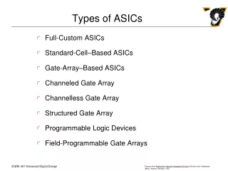
Outline • MEMS – Present & Future • 0) Introduction • 1) Present & Technology overview • 1.1) Pre-CMOS approach • 1.2) Intra-CMOS approach • 1.3) Post-CMOS approach • 1.4) Mass Sensitive Chemical Sensor • 1.5) Force Sensor Array • 2) Future • 2.1) CMOS MEMS based products • 2.2) CMOS NEMS • 2.3) Biotronics • 2.4) Siliconless CMOS MEMS Florian Bousquet, Department of Electronics and Telecommunication
Outline • Integrated Sensor Calibration • 0) Introduction • 1) 1-Dimentional calibration • 1.1) Calibration principle • 1.2) Mathematics • 1.3) Implementation • 2) 2-Dimentional Calibration • 2.1) Calibration principle • 2.2) Mathematics • 2.3) Implementation • Conclusion Florian Bousquet, Department of Electronics and Telecommunication
TFE 06 - ASICS FOR MEMS CMOS MEMS - Present & Future Integrated Smart Sensor Calibration Florian Bousquet, Department of Electronics and Telecommunication, NTNU
0) Introduction • All the IC nowadays and since 15 years : CMOS technology • High process yield, high reliability • Well established fabrications technologies ≠ • MEMS processes : only drive for a while by universities and defense labs • Due to “unstandardized” processes and low volumes ordered Florian Bousquet, Department of Electronics and Telecommunication
0) Introduction • In the mid-1990’s, development of: • Accelerometers for airbag deployment • DMD (Digital Micro mirror Devices) for image projection • Why? Integration of the MEMS structure into a basic CMOS process • Not only lowers manufacturing costs but also allows tighter integration of MEMS with ICs Florian Bousquet, Department of Electronics and Telecommunication
0) Introduction • Result: Reduced chip size Improvement device performance • Furthermore, high volume applications (inertial and pressure sensors) and applications requiring sensor arrays (DMDs) need both CMOS-MEMS processes. • Thus, CMOS-based MEMS is more and more used within CMOS processes to release devices. • An increasing number of Microsystem can be formed within the regular CMOS process sequence: Above all magnetic, optical and temperatures sensors. Florian Bousquet, Department of Electronics and Telecommunication
1) Technology overview • Process: • Based on depositing thin films of metal or crystalline material on a substrate • Then , applying patterned masks by photolithographic imaging • Finally, etching the films to the mask. • Wet etching : a liquid solution will dissolve the material • Dry etching : reactive ion etching (Released of beams and cantilever), sputter, and vapor phase etching • In the other hand, several devices (new ones) must be produced with additional micromachining and thin film deposition steps: • 1) Pre-CMOS approach • 2) Intermediate-CMOS Approach • 3) Post-CMOS Approach Florian Bousquet, Department of Electronics and Telecommunication
1.1)Pre-CMOS Approach • Structures of the MEMS are formed before the regular CMOS process sequence. • Avoid thermal budget constraints during the MEMS fabrication : typically, structures are buried and sealed. • And pre-processed wafer are used as starting materials for the subsequent CMOS process. Florian Bousquet, Department of Electronics and Telecommunication
1.2) Intra-CMOSapproach • Additional fabrication steps are performed in-between the regular CMOS steps. • More highly integrated process Better performances Why? Because the micro structures and electronics part are “closer together”. • And because inserting before the back end interconnect metallization ensures process compatibility with polysilicon. • Ex: Pressure sensors from Infineon Technologies and Freescale. Florian Bousquet, Department of Electronics and Telecommunication
1.3) Post-CMOS approach • Two possibilities: • MEMS structures are built from the CMOS layers (pressure, inertial, flow, chemical sensors). • Or built by additional layers deposited on top of the CMOS wafer (DMD by TI or Honeywell’s thermal imagers). • These two approaches are interesting because they can be entirely outsourced and so processed at any CMOS foundry. • Main Drawback: Stringent thermal budget, limiting temperatures to about 400°C Florian Bousquet, Department of Electronics and Telecommunication
1.4) Mass sensitive Microsensor • CMOS based sensor for detection of volatile organic compounds in air : • Based on cantilever beam vibrations and electro-thermal excitation detected by 4 Piezoresistors in Wheastone bridge and heating resistors. • Cantilever coated with chemical sensitive layer: upon absorption of analyte molecules, cantilever mass increases and its fundamental resonance frequency decrease. • This is recorded by an on-chip amplifying feedback circuit • Realized using a 0.8 µm CMOS technology of AMS Florian Bousquet, Department of Electronics and Telecommunication
1.5) Force sensor array • Sensor used for recording force images and force distance curves in Atomic Force Microscopy (AFM): • Consisting in 10 cantilevers with integrated thermal actuators, piezoresistive sensors and driving and signal conditioning circuitry • External controller applies heating power to the thermal actuators : Maintain constant cantilever defections • Piezoresistive output signal is amplified on-chip and applied to the external controller. • Operation time per cantilever: 100µs • Images area: 1.1 x 110 µm • Vertical resolution: 3 nm Florian Bousquet, Department of Electronics and Telecommunication
2) Future • 1) CMOS MEMS based products : • New products beyond the currently dominating pressure sensor and accelerometers • Based on the trends: • Systematic process development of laboratory CMOS MEMS for industrial mass production • Co-integration of digital interfaces and µcontrollers with microstructures less expensive and more powerful • Development of packaging to protect the vulnerable CMOS chip from environmental impact Florian Bousquet, Department of Electronics and Telecommunication
2) Future • 2) CMOS NEMS as platform for Nano: • High sensitivity to differents effects • They have to deliver more than a basic device function & some challenges have to be faced: • Interconnect challenge :Human is capable to handle mm sized objects and only few electrons generate signals • The « 300K » question : Problem of influence of the external conditions and thus find the right optimization • Everything nano? : Miniaturization is not a value by itself: it has a cost, and we have to focus on the crucial nano part and do the rest with µtechnology • But IC technology can bring the vast fabrication experience gained over the last decades, and it is to be noticed that gates thicknesses’ve reached the nano-level Florian Bousquet, Department of Electronics and Telecommunication
2) Future • 3) Micro Biotronics : BIO TRONICS • Biology • Biochemistry • Biomedical science… • Miniaturized Hardware: • Micro electronics • Mechatronics Biophysical and Biomedical microdevices MEMS for surgical sewing, Neuro MEMS, Biochemical sensors, Bio-mimetic devices… Florian Bousquet, Department of Electronics and Telecommunication
2) Future • 3) Micro Biotronics • Challenges are: • Requires operations in water abhorred by microelectronics • Living cells have to be kept alive by a mirofluidic supply system • Stability between biological and electronic materials • Limited lifetime of enzymes and antibodies Florian Bousquet, Department of Electronics and Telecommunication
2) Future • 4) Siliconless CMOS MEMS • Silicon might be expensive for MEMS requiring small parts of it. • Maybe make a whole µsystem out of polymer (plastic, glass) would be cost-effective. • Recent thin film transistors and organic circuits on flexible polymeric substrate have been demonstrate that was feasible. Florian Bousquet, Department of Electronics and Telecommunication
TFE 06 - ASICS FOR MEMS CMOS MEMS - Present & Future Integrated Smart Sensor Calibration Florian Bousquet, Department of Electronics and Telecommunication, NTNU
0) Introduction • Why calibration? • Sensor should provide correct transfert from the φ signal to the electrical output signal • Increase performance & reliability and so boost the MEMS market • BUT increase MEMS production costs : • It takes time and attention per individual sensor • Need several reference measurements and correction • Solution :Include at the sensor a programmable calibration facility (implemented as a digitally circuit integrated) • It does NOT eliminate the need to do calibration!! Florian Bousquet, Department of Electronics and Telecommunication
1) 1-Dimentional calibration • Calibration principle: • Normally : collecting a set of measurements data and then compute (complicated one!) correction formula • Here : Each measurement is directly used to compute one programmable coefficient in a correction function • And the next measurement makes use of this to compute another coefficient… but without affecting the previous calibration • By instance : • 1): Offset • 2): Gain • 3): Linearity • 4): … Florian Bousquet, Department of Electronics and Telecommunication
1) 1-Dimentional calibration • Mathematics: • Yref: reference signal (a1 is a dimensionless number) Florian Bousquet, Department of Electronics and Telecommunication
1) 1-Dimentional calibration Florian Bousquet, Department of Electronics and Telecommunication
1) 1-Dimentional calibration • Implementation: • Analog Signal Processor for Polynomial Sensor Calibration • Flow Diagram: Florian Bousquet, Department of Electronics and Telecommunication
1) 1-Dimentional calibration • Implementation: • Easy to implement on µcontroller (repetitive character) Or With Harware digital as well as analog • Following example: analog implementation with current signals • They can easily be added, substracted or multiplied (Kirschoff) • All the currents are represented by differential current and carried by common bias current Florian Bousquet, Department of Electronics and Telecommunication
1) 1-Dimentional calibration • Implementation (block diagram): Caption: Sensor Signal Calibration points Addition Substraction Correction coef Florian Bousquet, Department of Electronics and Telecommunication
1) 1-Dimentional calibration Florian Bousquet, Department of Electronics and Telecommunication
1) 1-Dimentional calibration Florian Bousquet, Department of Electronics and Telecommunication
2) 2-Dimensional Polynomial • Why 2 dimensions? • By instance, a pressure sensor: not only affected by pressure but also by temperature • Calibration principle: • Same method as before with a dimension more: • Select the error you want to correct (1° offset, 2° gain…) • Instead of correcting it once and pass through to the next error, make a set of corrections for a predefined number of temperatures values • So that the calibration function is equal to the desired function in all temperature calibration points • The results are better with that method (speed and error reduction) Florian Bousquet, Department of Electronics and Telecommunication
2) 2-Dimensional Polynomial • Mathematics : Florian Bousquet, Department of Electronics and Telecommunication
2) 2-Dimensional Polynomial Transfer & error surface before calibration Florian Bousquet, Department of Electronics and Telecommunication
2) 2-Dimensional Polynomial Transfer & error surface after calibration Florian Bousquet, Department of Electronics and Telecommunication
2) 2-Dimensional Polynomial • To prevent escalation of the polynomial factors in the formulas: • Make first a correction of the cross sensitivity (T°C in our case) before linearizing sensitivity of the input variable (pressure) • But complicated in our case: temperature is swept through the whole temperature range several times • And pressure cycles require less time for measurement than T°C • So the solution is: • Keep the order of corrected output values computation • But change the order of corrections coefficients computation by: • At T° t1, applying pressure p1 to calculate a11 and apply t2 to calculate a21… • Why can we make that? Because at the given T°, all the calibrations functions are equals!! It’s the definition of this method! Florian Bousquet, Department of Electronics and Telecommunication
2) 2-Dimensional Polynomial • Implementation: • Microcontroller-based pressure sensor system with digital Calibration Florian Bousquet, Department of Electronics and Telecommunication
2) 2-Dimensional Polynomial • Implementation: • Multiplexer makes possible to read out the T° sensor and the pressure sensor with only one ΔΣ AD converter • Calibration program and coefficients are stored in the µcontroller memory • Software is written in C language and is composed of 2 parts: • Calibration part : Compute calibration coefficients & measure output • Measurement part : Compute corrected values of pressure with equations • Functioning: • User have to enter reference datas for the whole calibration process • Once the number of cal. Points & reference signals are in the µcontroller, the system is totally autonomous and compute his own calibration coefficients and then compute the real measure of pressure. Florian Bousquet, Department of Electronics and Telecommunication
Conclusion • MEMS in the future will be more and more used since they are needed in a huge range of applications and since the IC processes can be used to produce some at a lower cost and with a best reliability • Calibration is a very important part but costly of the MEMS process • If the cost of such a process can be decreased and calibration made easier for the use, it would improve significantly the MEMS market • We’ve seen a method which is going in that sense Florian Bousquet, Department of Electronics and Telecommunication
Questions? Florian Bousquet, Department of Electronics and Telecommunication, NTNU