Download
1 / 9
130 likes | 186 Vues
What is the MEMS OXC? OXC based on 2D MEMS, 3D MEMS. HYC supplies MEMS Fiber Optical Switches,MEMS optical switch modules, MCS modules. Competitive prices from the leading fiber optical devices OEM/ODM manufacturer.

E N D
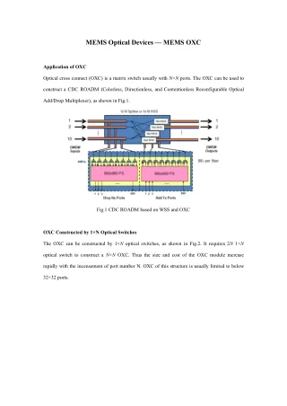
MEMS Optical Devices — MEMS OXC Application of OXC Optical cross connect (OXC) is a matrix switch usually with N×N ports. The OXC can be used to construct a CDC ROADM (Colorless, Directionless, and Contentionless Reconfigurable Optical Add/Drop Multiplexer), as shown in Fig.1. Fig.1 CDC ROADM based on WSS and OXC OXC Constructed by 1×N Optical Switches The OXC can be constructed by 1×N optical switches, as shown in Fig.2. It requires 2N 1×N optical switch to construct a N×N OXC. Thus the size and cost of the OXC module increase rapidly with the incensement of port number N. OXC of this structure is usually limited to below 32×32 ports.
Fig.2 An 8×8 OXC constructed by sixteen 1×8 optical switch OXC based on 2D MEMS The second approach for a OXC is a cross-bar optical switch based on a MEMS mirror array. In 1996, H. Toshiyoshi and H. Fujita from University of Tokyo reported the first cross-bar MEMS optical switch with potential for matrix scaling up, as shown in Fig.3. The reported device has two inputs and four outputs. The switching is realized with four mirrors. Each mirror has two states, lying horizontally (Off-state) to let pass the optical beam or standing vertically (On-state) to reflect the optical beam . Fig.3 Structure of the first cross-bar matrix switch based on MEMS torsion mirror The SEM photos and structure of the MEMS torsion mirror for above cross-bar optical switch is
shown in Fig.4. The mirror is supported by a polysilicon beam. It stays horizontally when no electrical voltage is applied to the electrodes and stands vertically when driven by electrostatic force . Fig.4 SEM photos and structure of the MEMS torsion mirror L.Y. Lin, et. al., reported the first 2D MEMS matrix switch, as shown in Fig.5. A N×N mirror array is required for a N×N optical switch. All the optical paths are in a 2D plane, which is why it is call 2D MEMS optical switch[3]. Fig.5 Structure of the first 2D MEMS matrix switch The switching is realized by micro-actuated mirrors as shown in Fig.6. The mirror is hinged on the base. Two pushrods are designed to hinge the mirror on one end and a translation plate on the other end. The translation plate is driven by a scratch drive actuator and pulls the mirror forward. The mirror rotates when it is pulled.
Fig.6 Schematic drawing of the micro-actuated mirror[3] In 2002, Li Fan et. al. from OMM, Inc. reported a MEMS mirror array for matrix switch, as shown in Fig.7. Fig.7 2D MEMS mirror array by Li Fan et. al. from OMM, Inc. The 2D MEMS matrix switches are characterized by simple structure and easy assembly, while their scalability is limited. As we can see in Fig.5, the lengths of light paths for different links are quite different, which introduces coupling loss and loss uniformity. The tolerance to light path difference depends on the beam size in the free space optics. An optical beam with small radius ω0 is more divergent according to Eq. (1) and the collimation length is shorter according to Eq. (2). (1) 2 0 0z (2) The coupling between two single mode fibers (SMF) is shown in Fig.8(a). The coupling loss
increases rapidly with the increment of the separation between the two fibers. The separation between two SMF is limited to <20μm. In order to increase the fiber separation to accommodate free space optics, thermally expanded core (TEC) fibers and lensed fibers are employed, as shown in Fig.8(b) and Fig.8(c), respectively. The TEC fibers and lensed fibers expand the beam size for free space transmission. The separation between two TEC fibers is ~10mm and that between two lensed fibers is ~50mm. For some applications that require longer free space light paths (such as 3D MEMS optical switches to be mentioned below), the collimating lenses are required, as shown in Fig.8(d). Fig.8 Fiber coupling methods Thus we know, with the employment of TEC fibers or lensed fibers in a 2D MEMS optical switch, the free space light paths are extended to accommodate more MEMS mirrors and thus the optical switch is scaled up. However, the maximum beam size is limited by the mirror size, which depends on the MEMS design and process. The mirror size is usually required to be Ф>3ω0 to reflect >99% of the optical power. Thus the maximum number of ports is usually limited to be 32×32 for a 2D MEMS optical switch. OXC based on 3D MEMS In order to further scale up the OXC, 3D MEMS optical switches are developed. The basic structure of a 3D MEMS OXC by NTT Laboratories is shown in Fig.9, which consists of two
MEMS mirror arrays and two 2D fiber collimator arrays. Each input fiber collimator corresponds to one mirror in the first MEMS mirror array and each output fiber collimator corresponds to one mirror in the second MEMS mirror array. All the mirrors on the MEMS chips have two rotation axes, as shown in Fig.10. Fig.9 Basic structure of a 3D MEMS OXC by NTT Laboratories Fig.10 SEM photos of the MEMS mirror array and single mirror with two axes The optical beam from each input is independently controlled by a mirror in the first MEMS chip and is directed to another mirror (corresponding to the destination output) in the second MEMS chip. The second mirror rotates around two axes and adjusts the reflected beam toward the output fiber collimator. Thus by control of the two MEMS chips, optical signal from any input can be switched to any output. The 3D MEMS OXC was fabricated by NTT laboratories in Oct., 2003. The photo of the sample is shown in Fig.11.
Fig.11 3D MEMS OXC sample fabricated by NTT Laboratories V. A. Aksyuk et. al. from Bell Laboratories reported a 3D MEMS OXC in Apr., 2003, which was prior to the OXC reported by NTT laboratories. We first mentioned the latter because of its simple structure and ease for analysis. The OXC structure and sample by Bell Labs are shown in Fig.12 and Fig.13, respectively. It includes two MEMS mirror arrays, two 2D fiber arrays and one Fourier lens. Each input-output link is constructed through one mirror in the first MEMS chip and another mirror in the second MEMS chip. Fig.12 Structure of the 3D MEMS OXC by Bell Laboratories
Fig.13 Photo of the 3D MEMS OXC by Bell Laboratories In 2012, Yuko Kawajiri et. al. from NTT labs reported another 3D MEMS OXC, as shown in Fig.14 and Fig.15. A toroidal concave mirror is employed instead of a Fourier lens. The toroidal design of the concave mirror is to reduce the off-axis aberration of edge ports . Fig.14 Structure of the 3D MEMS OXC by NTT Laboratories
Fig.15 Photo of the 3D MEMS OXC by NTT Laboratories The principles of OXC in Fig.12 and Fig.14 are similar. Comparing to the structure in Fig.9, the beam size in free space optics is larger and thus loss is reduced. What’s more, the structure in Fig.9 require that the MEMS mirrors have larger rotation angle, which adds to difficulty for MEMS design. About HYC HYC Co., Ltd was founded in 2000. It is a leading passive optical devices OEM/ODM manufaturer in the global industry, focusing on R&D, manufacturing, sales and service of passive devices for optical communication. The company's main products are: optical fiber connectivity products, WDM wavelength division multiplexers, PLC optical splitters, and MEMS optical switches, which is widely used in 4G / 5G networks, Telecom, Data centers, etc. http://www.hyc-system.com


![Modeling MEMS Sensors [SUGAR: A Computer Aided Design Tool for MEMS ]](https://cdn2.slideserve.com/5124381/modeling-mems-sensors-sugar-a-computer-aided-design-tool-for-mems-dt.jpg)