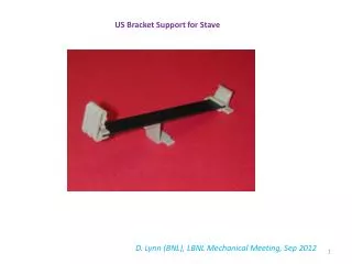
Electrical and Optical Readout Setup for DCS in Stave 0 - August 2011 Overview
This document outlines the electrical and optical readout procedures for the DCS of Stave 0 as of August 4, 2011. It emphasizes the immediate need for high voltage power supplies, including the ISEG 1kV and 500V models, and details interlock mechanisms for safety, including temperature monitoring. It also discusses the integration of the new SCOL and the necessity of completing the DCS GUI to manage and switch parameters seamlessly as project components evolve. Coordination with personnel knowledgeable in DCS hardware is recommended to ensure smooth operations.

Electrical and Optical Readout Setup for DCS in Stave 0 - August 2011 Overview
E N D
Presentation Transcript
DCS for stave-0 Susanne Kersten August 4, 2011
1. Electricalreadout HV • power supplystartwithpixel (iseg 700 V, 4 mA) • Buy final power supplyasap (iseg 1kV, respectively 500V) • No HV-PP4 necessary LV • Pixel and IBL the same Wiener PS • Start withpixel spare • LV-PP4 • startwithpixelfor passive splitting • Move to IBL whenavailable • PP2 Mauro foreseestostartwithmodifiedpixelhardware
1. Electricalreadout • Temperaturemonitoringand interlock • Useone block ofpixel BBIM (building block interlock andmonitoring) • Usespecialhardwired interlock • Ifother power suppliesareused, verifythat interlock inputavailable! • Environmental temperaturemonitoring • Usepixel BBM • Other needs, sensors?
2. Optical readout • New SCOL available in October • Old PP2 boardhasfittingVvdcchannel and: • Involve Petr (knows SR1 servicesand DCS hardwarevery well)!
DCS software • DCS GUI: • onepanelcollecting all quantitiesrelatedtoone half stave • Allowsforswitch on/off • Allowstomodifysetvalues • Whenis DCS GUI required? • As soonas FE-I4B comesintothegame • handlingoftemp. info must be investigated1!